Image processing apparatus and method, program and storage medium
a technology of image processing and image, applied in the field of image processing apparatus, can solve the problems of large memory capacity, long time to transmit data, and difficulty in obtaining information from characters or lines included in images
- Summary
- Abstract
- Description
- Claims
- Application Information
AI Technical Summary
Problems solved by technology
Method used
Image
Examples
first embodiment
[First Embodiment]
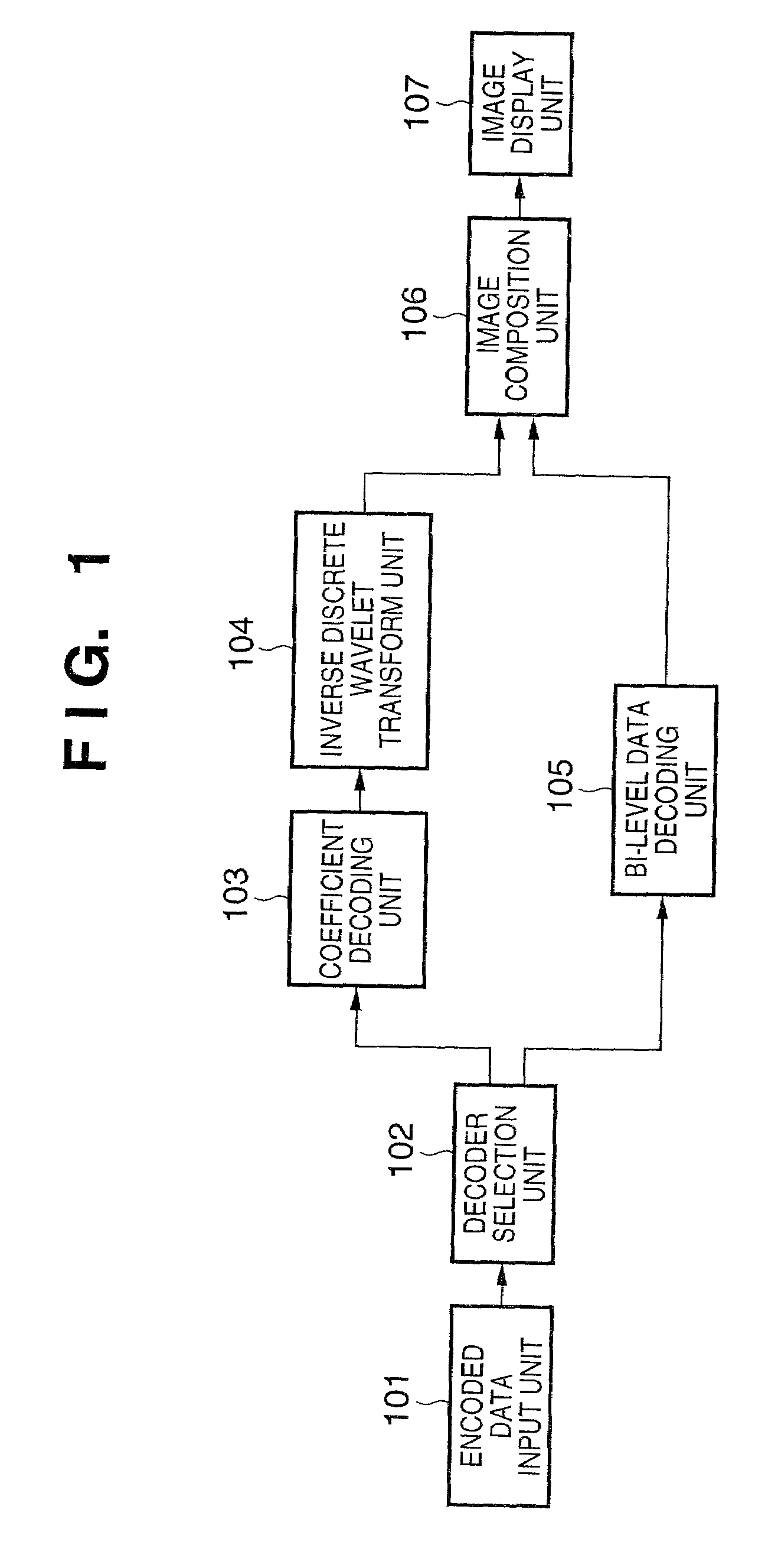
[0044]FIG. 1 is a block diagram showing a schematic configuration of an image decoding apparatus in this embodiment. In the figure, reference numeral 101 denotes an encoded data input unit, 102 a decoder selection unit, 103 a coefficient decoding unit, 104 an inverse discrete wavelet transform unit, 105 a bi-level data decoding unit, 106 an image composition unit, and 107 an image display unit.
[0045]In this embodiment, the explanation will be made with an example that monochrome image data in which the luminance value of one pixel is represented by 8 bits is decoded and displayed. However, it is apparent from the following description that the embodiment is not limited to this example and it is applicable to the cases where luminance value is represented by other than 8 bits, for example, 4 bits, 10 bits or 12 bits as well as the cases of color image data in which each pixel is represented by multiple color components such as RGB, YCrCb and CMYK. It is also apparen...
second embodiment
[Second Embodiment]
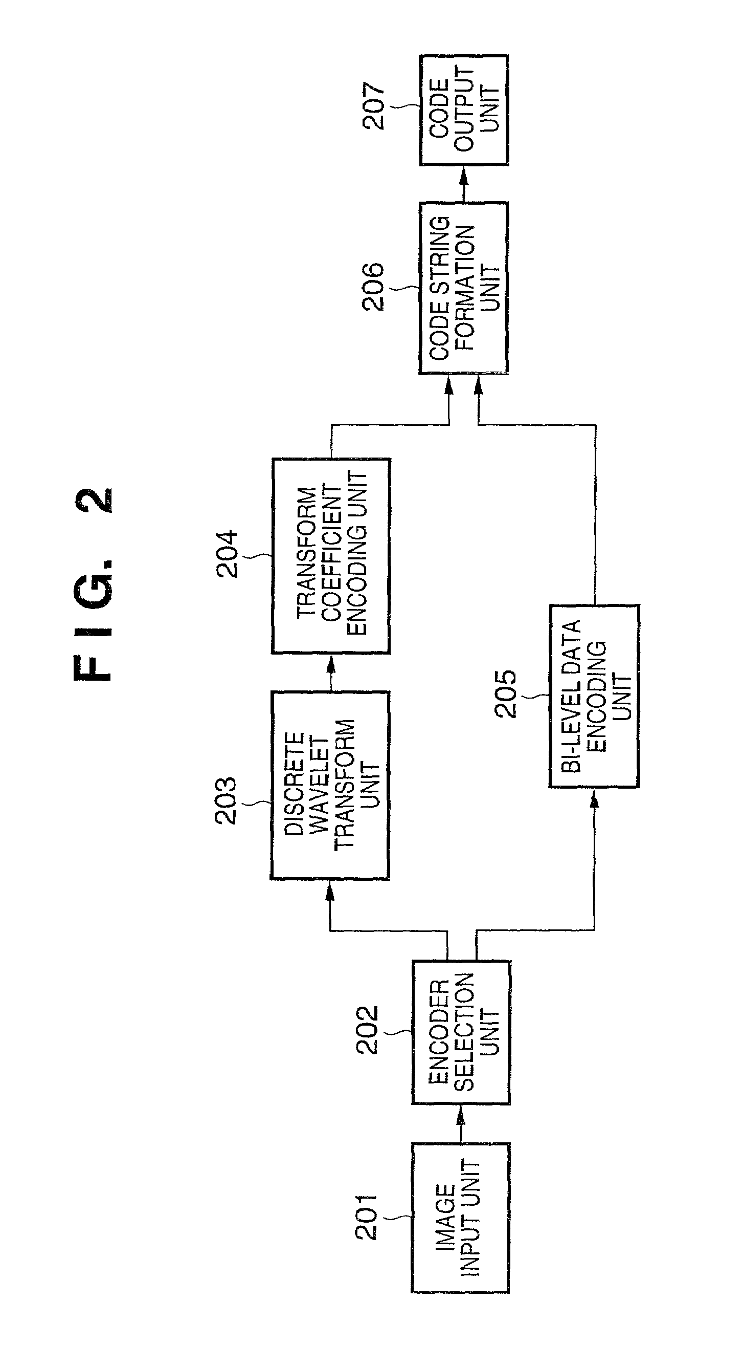
[0095]FIG. 14 is a block diagram showing a schematic configuration of a system for encoding and decoding images in the second embodiment. Items common to those in the block diagrams in FIGS. 1 and 2 showing schematic configurations of the image encoding apparatus and image decoding apparatus will be given the same reference numbers and not explained in further detail.
[0096]In FIG. 14, reference numeral 1401 denotes a tile dividing unit, 1402 a secondary storage device, 1403 an encoded data readout unit and 1404 a tile connecting unit. The encoded data readout unit 1403 can serve as the encoded data input unit 101.
[0097]In this embodiment, just as in the first embodiment described above, it is supposed that monochrome image data in which the luminance value of one pixel is represented by 8 bits is encoded and decoded. However, it is apparent from the following description that the embodiment is not limited to this example and it is applicable to the cases where lum...
third embodiment
[Third Embodiment]
[0114]As shown in FIG. 11, in the first and second embodiments, the code string is constituted by placing the multi-level image encoded data first and the bi-level image encoded data subsequent thereto in each level. In this embodiment, the order is reversed: the bi-level image encoded data is placed first and the multi-level image encoded data is placed subsequent thereto as shown in FIG. 17.
[0115]The system configuration in this embodiment is identical with that described in the second embodiment; therefore, further explanation will be omitted. However, only the procedures in the image composition unit 105 are slightly changed to generate a composite image by combining, at a point in time when the decoded bi-level image data is transmitted from the bi-level data decoding unit 105, an image generated by scaling to double a multi-level image currently displayed and the bi-level image, and the composite image is transmitted to the image display unit 107. According t...
PUM
 Abstract
Description
Claims
Application Information
 - R&D
- Intellectual Property
- Life Sciences
- Materials
- Tech Scout
- Unparalleled Data Quality
- Higher Quality Content
- 60% Fewer Hallucinations
Browse by: Latest US Patents, China's latest patents, Technical Efficacy Thesaurus, Application Domain, Technology Topic, Popular Technical Reports.
© 2025 PatSnap. All rights reserved.Legal|Privacy policy|Modern Slavery Act Transparency Statement|Sitemap|About US| Contact US: help@patsnap.com


