Detecting network power connection status using AC signals

a network power connection and ac signal technology, applied in the field of supplying dc power, can solve the problems of a certain amount of current and no simple way under the current standard to automatically restore power

Active Publication Date: 2006-01-10
CISCO TECH INC
View PDF17 Cites 139 Cited by
  • Summary
  • Abstract
  • Description
  • Claims
  • Application Information

AI Technical Summary

Benefits of technology

[0028]supplying DC power to at least one of the nodes via the communication cabling over at

Problems solved by technology

The mechanism requires, however, that the PD consume a certain amount of current at all times, even when it is

Method used


Image

  • Detecting network power connection status using AC signals
  • Detecting network power connection status using AC signals
  • Detecting network power connection status using AC signals

Examples


Embodiment Construction

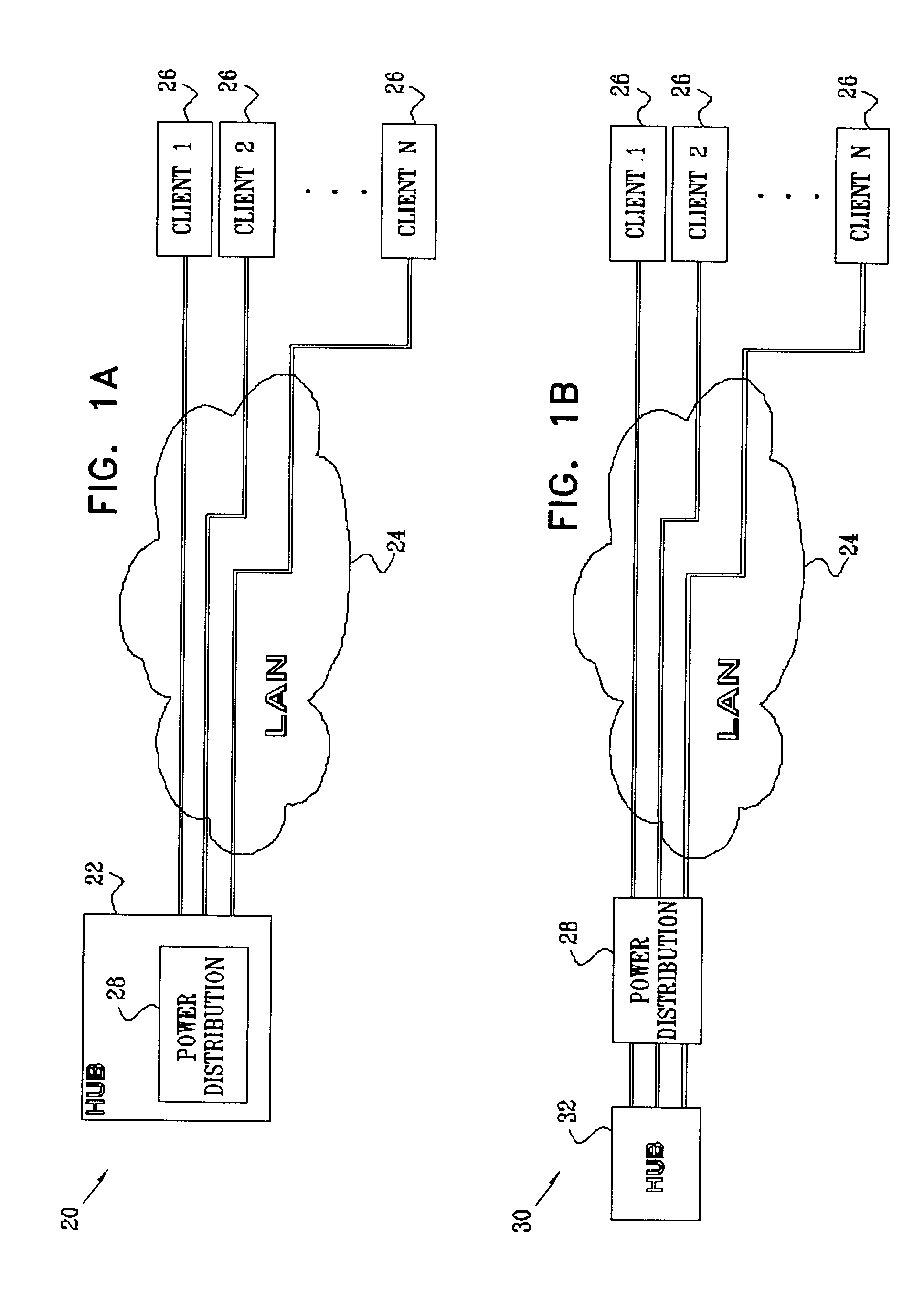
[0039]FIGS. 1A and 1B are block diagrams that schematically illustrate Power over LAN systems 20 and 30, respectively, based on the principles of the present invention. FIG. 1A shows an end-span configuration, in which a switching hub 22 comprises a master power distribution unit 28. Hub 22 communicates over a LAN 24 with single or multiple clients 26. FIG. 1B shows a mid-span configuration, in which unit 28 is located between a switching hub 32 and clients 26. In both embodiments, unit 28 supplies DC power over the LAN cables to those of clients 26 that are configured as PDs. In order to control the distribution of DC power to the clients, unit 28 couples a periodic, time-varying signal onto the LAN cables, and senses the resulting time-varying voltage on its output ports, as described in detail hereinbelow.

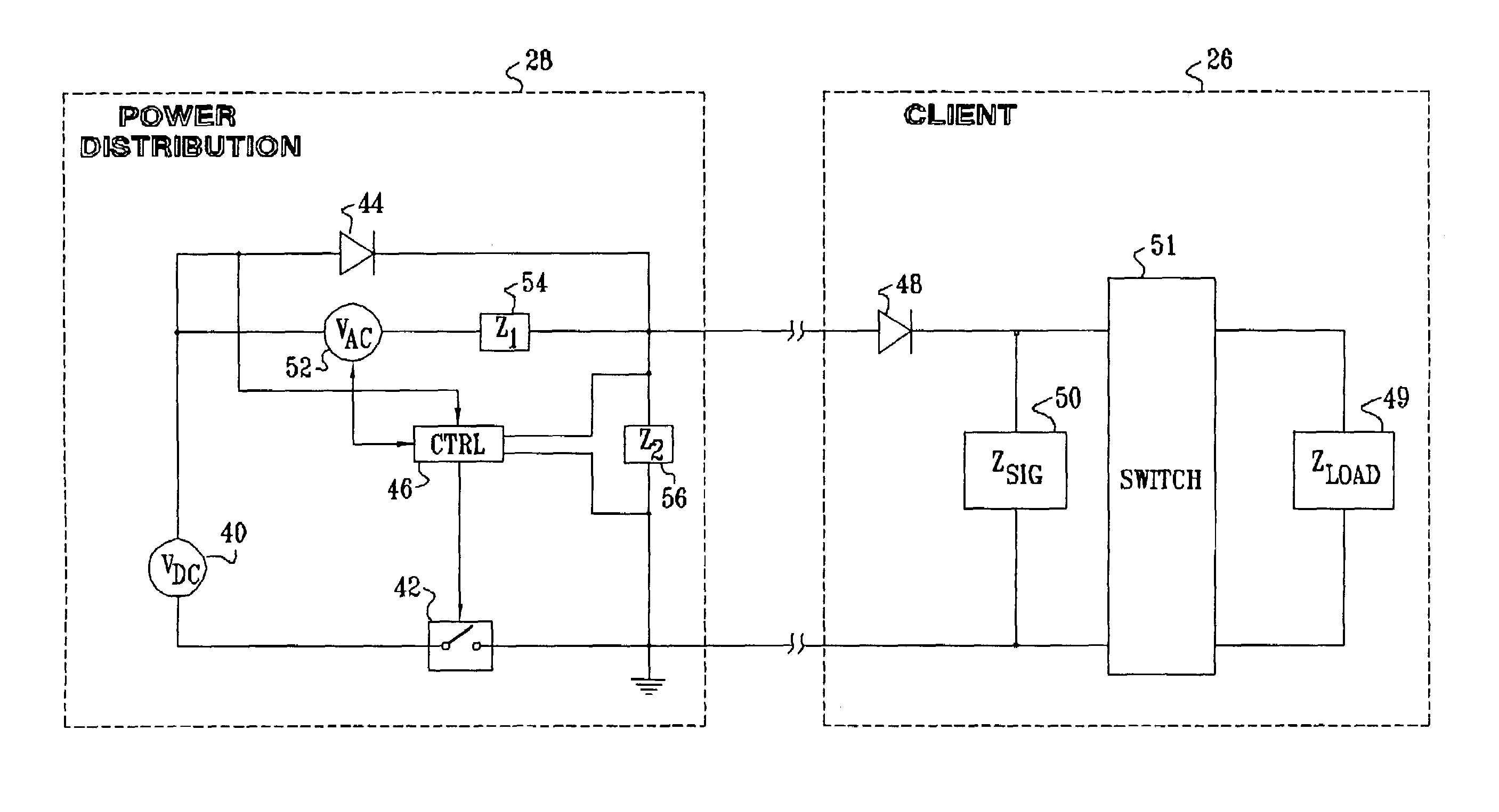
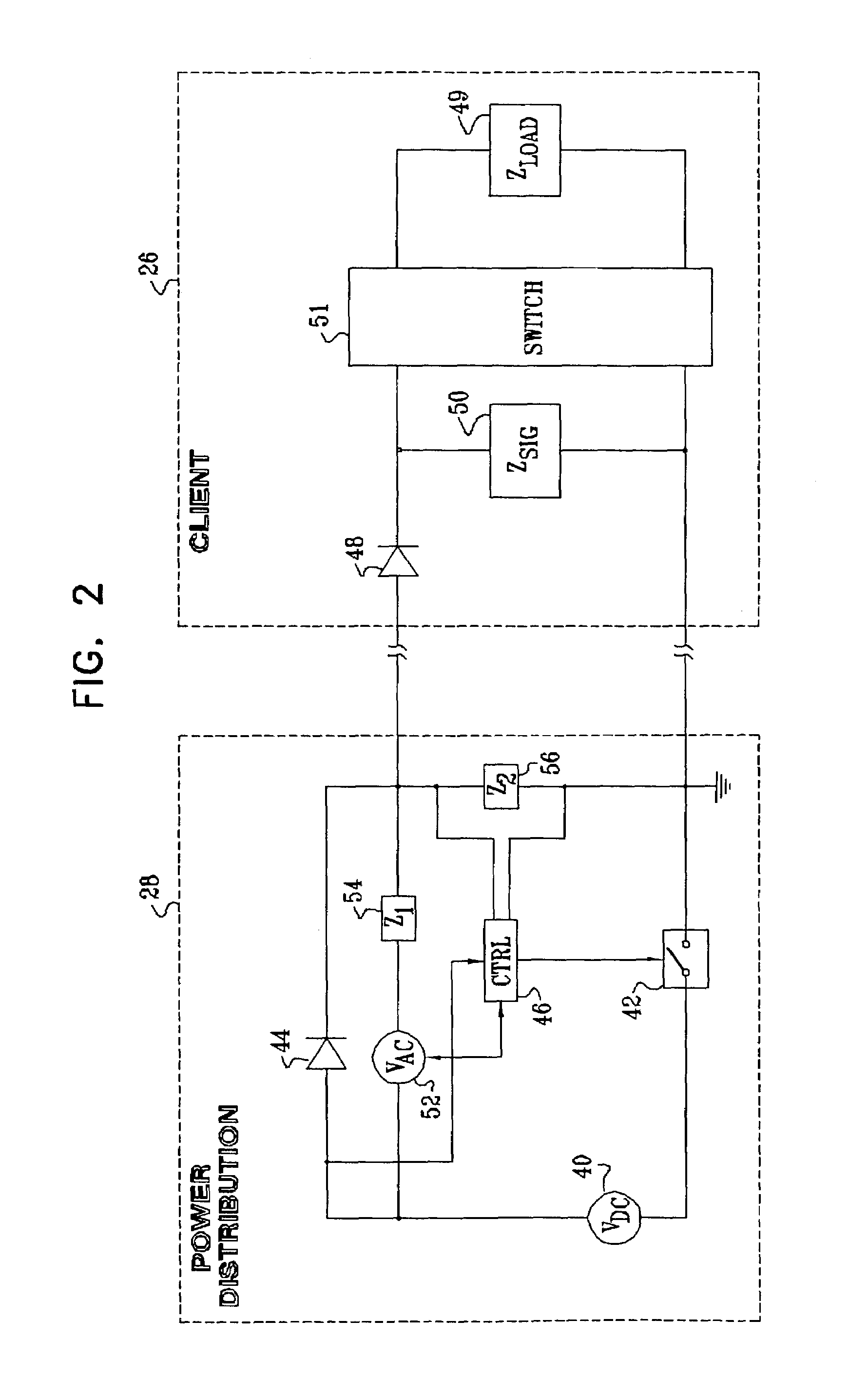
[0040]FIG. 2 is a block diagram that schematically shows details of power distribution unit 28 with one of clients 26, in accordance with a preferred embodiment of the present i...


PUM


Abstract

A power supply subsystem for use in a local area network (LAN) includes a direct current (DC) power source, which supplies DC power to at least one of the nodes via at least one of the wire pairs used in communication cabling of the LAN, substantially without interfering with data communications. A signal generator generates a periodic time-varying signal and couples the time-varying signal into the at least one of the wire pairs. A control unit senses a time-varying voltage on the at least one of the wire pairs due to the time-varying signal generated by the signal generator, and responsive to the sensed time-varying voltage, controls the DC power supplied to the at least one of the nodes by the DC power source.

Description

CROSS-REFERENCE TO RELATED APPLICATION[0001]This application claims the benefit of U.S. Provisional Patent Application No. 60 / 353,780, filed Feb. 1, 2002, which is incorporated herein by reference.FIELD OF THE INVENTION[0002]The present invention relates generally to supplying DC power over a local area network (LAN), and specifically to methods and circuitry for detecting connection and disconnection of powered devices on the LAN.BACKGROUND OF THE INVENTION[0003]Power over LAN™ is a new technology that enables DC power to be supplied to Ethernet data terminals over ordinary Category 5 cabling. This technology enables the terminals to receive their operating power over the same Ethernet local area network (LAN) that they use for data communication. It thus eliminates the need to connect each terminal to an AC power socket, and to provide each terminal with its own AC / DC power converter. Further aspects of this technology are described in PowerDsine Application Note 115, entitled “Po...

Claims


Application Information

Patent Timeline
IPC IPC(8): G06F1/32H04L12/10H04L12/28H04L12/56
CPCH04L12/10H04L49/351H04L12/28H04L49/40
Inventor DARSHAN, YAIRFERENTZ, ALONKORCHERAZ, DROR
Owner CISCO TECH INC
Why Eureka
Try Eureka