
Methods and apparatus for determining scrubber brush pressure

Active Publication Date: 2006-01-17
APPLIED MATERIALS INC
View PDF3 Cites 25 Cited by
  • Summary
  • Abstract
  • Description
  • Claims
  • Application Information

AI Technical Summary

Problems solved by technology

However, the present inventors have recognized that a scrubber is a hostile environment for pressure sensors, and that conventional pressure sensors may deteriorate during use in a scrubber and interfere with operation of the scrubber's pressure regulation system.

Method used


Image

  • Methods and apparatus for determining scrubber brush pressure
  • Methods and apparatus for determining scrubber brush pressure
  • Methods and apparatus for determining scrubber brush pressure

Examples


Embodiment Construction

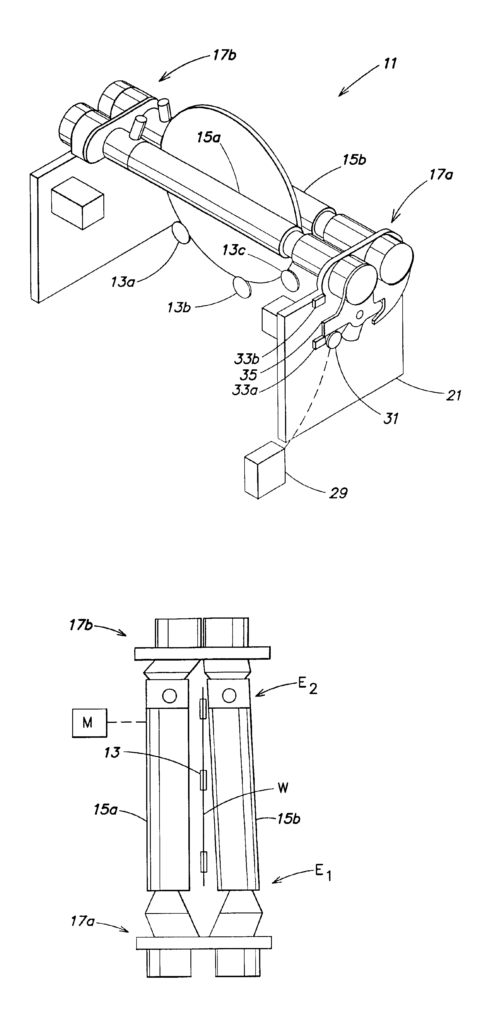
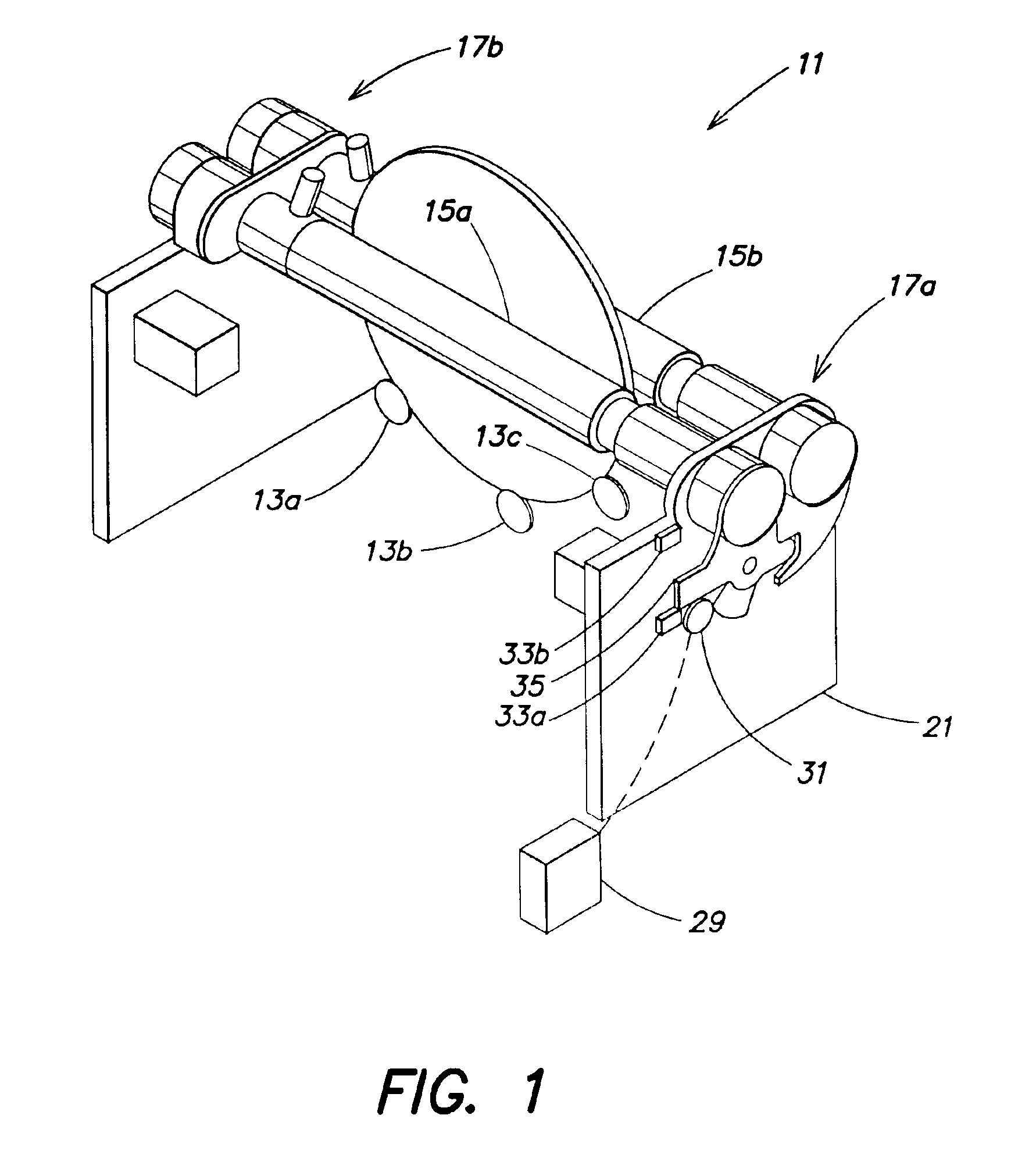
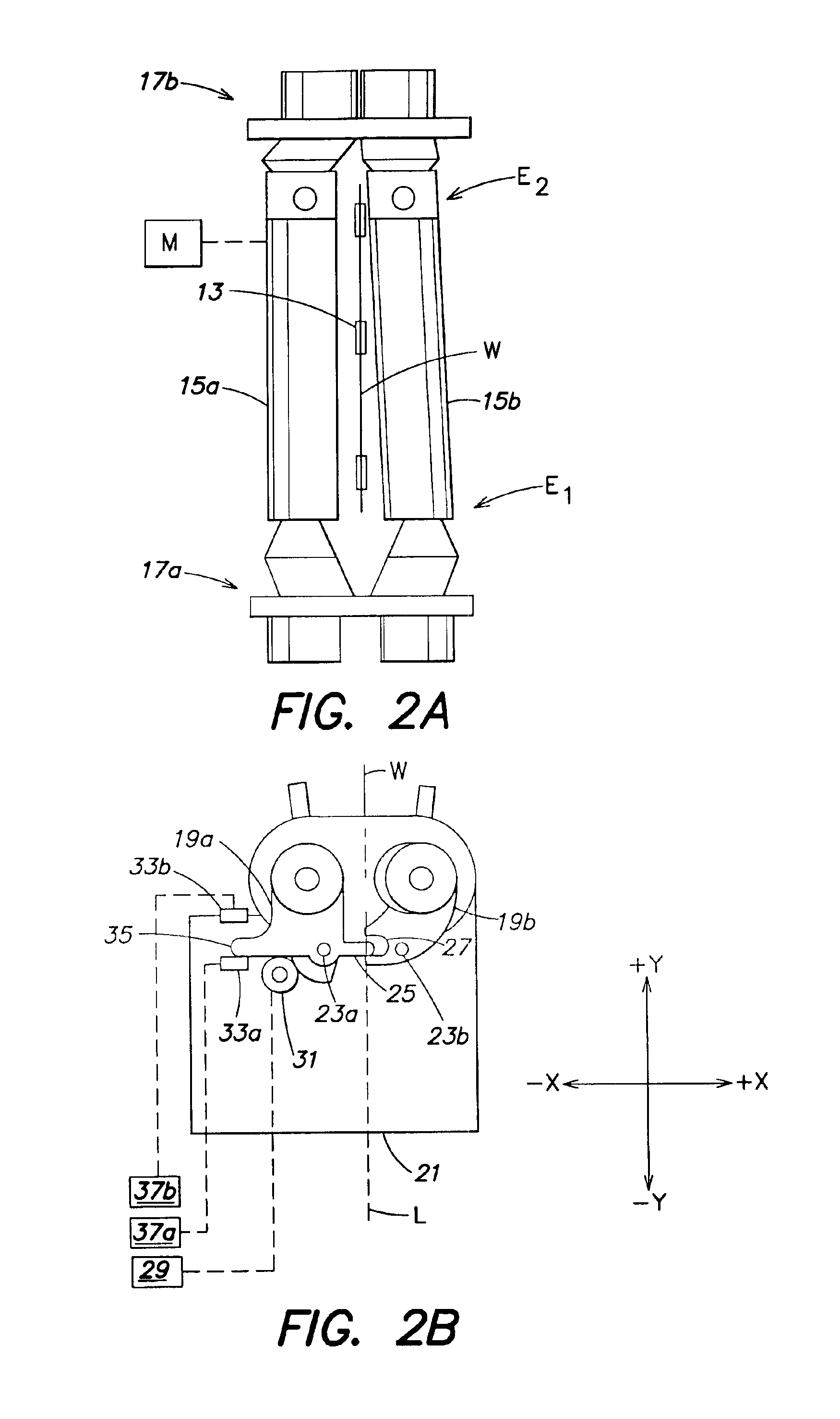
[0019]FIG. 1 is a side perspective view of an inventive scrubber 11 taken from above, and FIGS. 2A-B and 3A-B are a top plan view, and a side elevational view of the scrubber 11, shown in an opened position and a closed position, respectively. As shown in FIG. 1, the inventive scrubber 11 comprises a plurality of rollers 13a-c on which a wafer W may be supported and / or rotated via one or more roller motors (not shown). Other numbers and / or positions of rollers may be employed. A pair of scrubber brushes 15a-b is located above the rollers 13a-c with the brushes 15a-b positioned so as to extend along opposite sides of the wafer W. A motor M is coupled to and is adapted to drive the scrubber brushes 15a-b at a desired rotational speed (e.g., typically about 50 to 700 RPM, although other speeds may be used). Alternatively, multiple motors may be employed to rotate the scrubber brushes 15a-b (e.g., a separate motor for each scrubber brush).

[0020]Each of the scrubber brushes 15a-b is moun...


PUM


Abstract

In a scrubber adapted to clean a semiconductor wafer, the torque of a brush rotation motor is monitored while a scrubber brush is in contact with the wafer and is being rotated by the motor. The position of the brush relative to the wafer may be adjusted based on the monitored torque to regulate the pressure applied to the wafer by the brush. Open loop positioning or closed loop control may be employed.

Description

[0001]This application claims priority from U.S. Provisional Patent Application Ser. No. 60 / 339,992, filed Oct. 30, 2001, which is hereby incorporated by reference herein in its entirety.FIELD OF THE INVENTION[0002]The present invention is concerned with manufacturing of semiconductor devices, and is more particularly concerned with cleaning a semiconductor wafer by applying at least one rotating brush to the wafer.BACKGROUND OF THE INVENTION[0003]Known devices, sometimes referred to as scrubbers, are often employed to clean semiconductor wafers at one or more stages of a semiconductor device manufacturing process. For example, a scrubber may be employed to clean a wafer after chemical mechanical polishing (CMP) of the wafer. Known scrubbers employ one or more scrubber brushes that are rotated while in contact with the wafer to thereby clean the wafer.[0004]It is also known to adjust the position of a scrubber brush relative to a wafer in response to a pressure sensor which detects ...

Claims


Application Information

Patent Timeline
IPC IPC(8): B08B11/00B08B1/04
CPCH01L21/67046B08B1/04B08B1/32
Inventor SUGARMAN, MICHAEL N.GALBURT, VLADIMIR
Owner APPLIED MATERIALS INC
Features
  • Generate Ideas
  • Intellectual Property
  • Life Sciences
  • Materials
  • Tech Scout
  • Unparalleled Data Quality
  • Higher Quality Content
  • 60% Fewer Hallucinations
Learn More