Planting receptacle assembly and a method for planting

a technology of plant receptacles and planting containers, which is applied in the direction of horticulture, seed and root treatment, sewer pipelines, etc., can solve the problems of limiting the types of designs, requiring a relatively large amount of maintenance of growably contained planting materials, and unaesthetically overall appearan

Inactive Publication Date: 2006-01-17
COCHRAN BRADLEY
View PDF69 Cites 12 Cited by
  • Summary
  • Abstract
  • Description
  • Claims
  • Application Information

AI Technical Summary

Benefits of technology

[0007]It is a first non-limiting advantage of the present invention to provide a planting assembly which overcomes at least some of the previously delineated disadvantages of prior planting assemblies.
[0008]It is a second non-limiting advantage of the present invention to provide a method for planting which overcomes some or all of the previously delineated methods for planting which utilized prior planting assemblies.
[0009]It is a third non-limiting advantage of the present invention to provide a planting assembly which may be formed into substantially any desired shape and which is securely and selectively anchored into the ground.
[0010]According to a first non-limiting aspect of the present invention, a planting receptacle assembly is provided. Particularly, the planting assembly comprises a first flexible trough member having a generally semi-circular reception portion and a pair of protruding and curled lips which are longitudinally coextensive to said first flexible trough member and which are formed on opposed edges of said generally semi-circular reception portion; and a second flexible trough member which is substantially identical to said first flexible trough member and which is selectively and removably interconnected to said first flexible trough member.
[0011]According to a second non-limiting aspect of the present invention, a method for planting is provided. Particularly, the method includes the steps of forming a flexible trough having a first and a second end and a generally semi-circular reception portion; digging a trench in a desired shape; placing said flexible trough into said trench; forming a divot member; attaching said first end to said second end, effective to capture said divot member between said attached first and second ends; and anchoring said divot member within said trench, effective to anchor said flexible trough within said trench.
[0012]According to a third non-limiting aspect of the present invention, a method for planting is provided. Particularly, the method includes the steps of forming a flexible trough member having a generally semi-circular reception portion including a plurality of drainage holes, said flexible trough member further having a pair of opposed raised lips and a plurality of liquid emanation holes which are linearly coextensive to said pair of opposed raised lips and which reside above said generally semi-circular reception portion; cutting said flexible trough member into a pair of members; digging a first trench; placing a first of said pair of members into said first trench; digging a second trench which is nested in relation to said first trench; placing a second of said pair of members into said second trench; and coupling a first of said raised lips of said first of said pair of members with a first of said raised lips of said second of said pair of members; effective to couple said first of said pair of members to said second of said pair of members.

Problems solved by technology

First, by way of example and without limitation, these prior planting assemblies are formed from a relatively rigid material and have a relatively rigid linear structure. Hence, these prior planting assemblies are not readily useable to form intricate or accurate patterns, thereby substantially and undesirably limiting the types of designs or patterns which may be formed by use of the contained planting material. This is a significant drawback since one of the major motivations for using these prior planting assemblies is to provide an aesthetically pleasing overall appearance and this is largely achieved by the choice of the contained material (e.g., the color and texture of the growably contained planting material), as well as from the pattern that the assemblies respectively forms.
Secondly, by way of example and without limitation, these prior planting assemblies are not capable of being securely anchored into the ground. Thus, as ambient weather conditions change (e.g., as the soil conditions change) these planting assemblies become dislodged and create an undesirable and unaesthetically pleasing overall appearance. Further, these prior planting assemblies become easily dislodged from contact with landscapers or landscape implements (e.g., a lawnmower), thereby further and undesirably easily providing an unaesthetically overall appearance.
Thirdly, by way of example and without limitation, these prior planting assemblies do not generally distribute water or other liquid type of nutrients to the contained planting material, thereby requiring a relatively large amount of maintenance to the growably contained planting material.

Method used


Image

  • Planting receptacle assembly and a method for planting
  • Planting receptacle assembly and a method for planting
  • Planting receptacle assembly and a method for planting

Examples


Embodiment Construction

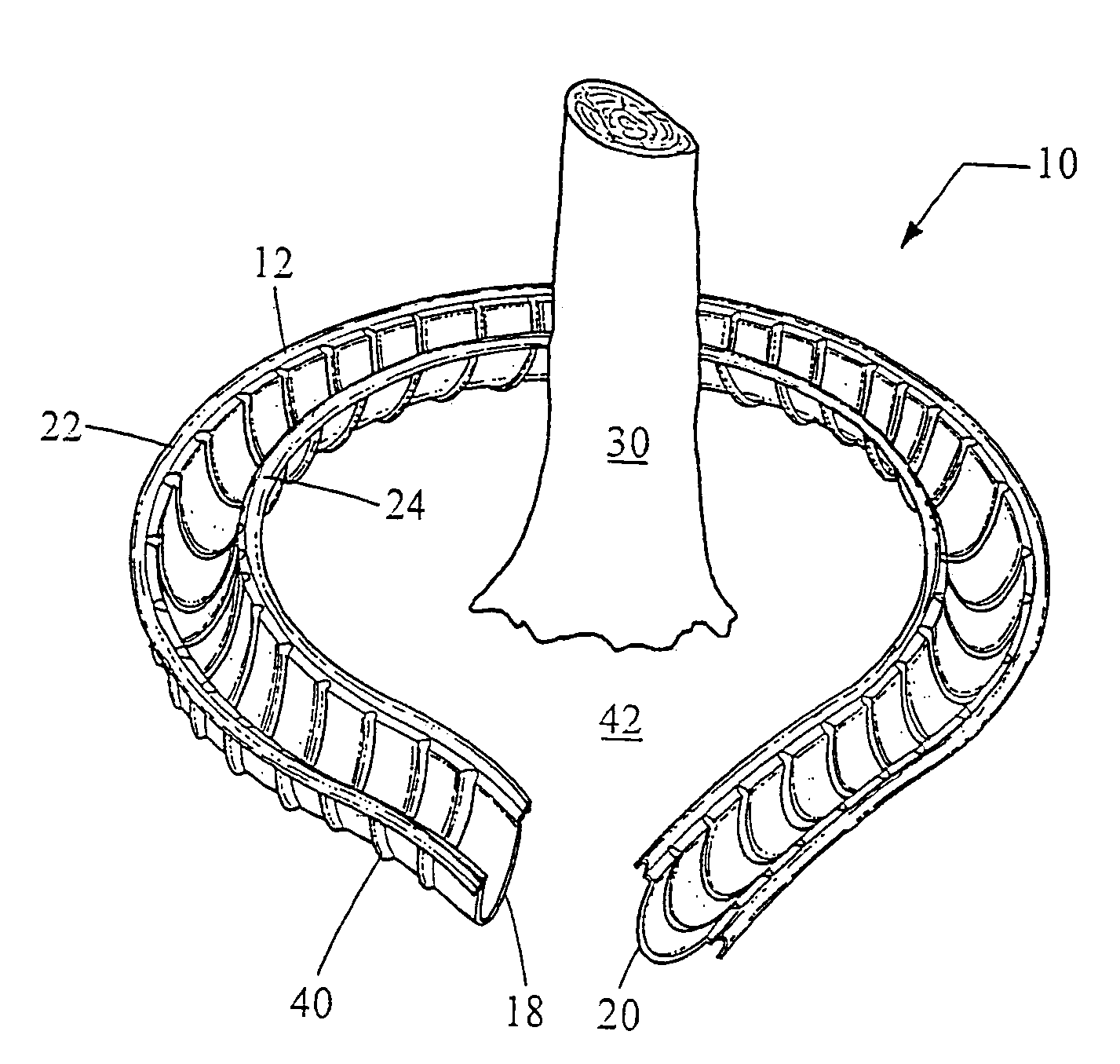
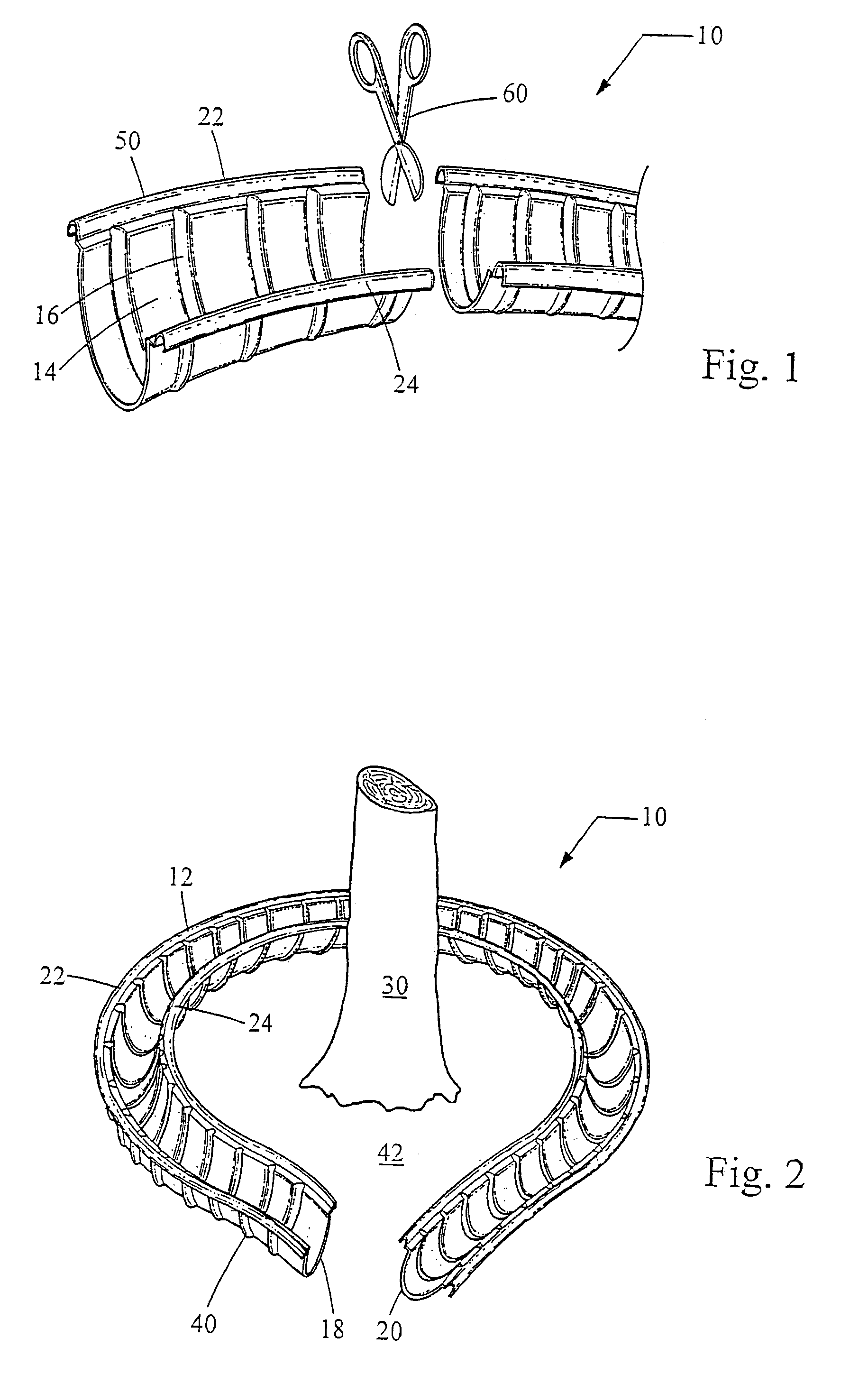
[0028]Referring now to FIGS. 1 and 2, there is shown a planting assembly 10 which is made in accordance with the teachings of the preferred embodiment of the invention.

[0029]As shown, planting assembly 10 comprises a very flexible trough member 12 having a generally semi-circular shaped planting reception portion 14 which includes integrally formed and equidistantly spaced strengthening ribs 16. In the most preferred embodiment of the invention, the trough member 12 is formed from a very soft plastic or composite type material, although other materials may be used in other non-limiting embodiments. The trough member 12 further has opposed and “open” ends 18, 20.

[0030]It should be appreciated that, in other non-limiting embodiments of the invention, the ribs 16 may be constructed from either a more flexible material than that which is used to construct the trough member 12 or be constructed to be thinner than the thickness of the trough member 12. In these other non-limiting embodime...


PUM


Abstract

A planting assembly (10) including a flexible trough member (12) which may selectively form a plurality of members which may be then selectively interconnected in any desired manner.

Description

FIELD OF THE INVENTION[0001]The present invention generally relates to a planting receptacle assembly and to a method for planting and more particularly by way of example and without limitation to an assembly which may be used to selectively create complex planting designs in a relatively efficient manner and which further allows the design to remain stable by allowing the assembly to remain securely anchored into the ground.BACKGROUND OF THE INVENTION[0002]A planting assembly is typically used to receive one or more plants and is secured into the ground, thereby being effective to allow the contained plants to be growably deployed within a certain area, such as and without limitation a landscape “zone” or some other “pre-assigned” or pre-designated area. While prior planting assemblies do allow for the selective deployment of plants within or along a certain area or border, they suffer from some drawbacks.[0003]First, by way of example and without limitation, these prior planting a...

Claims


Application Information

Patent Timeline
Patent Type & Authority Patents(United States)
IPC IPC(8): A01G9/02A01C1/00A01C23/00A01G9/10A01G9/28
CPCA01G9/027
Inventor COCHRAN, BRADLEY
Owner COCHRAN BRADLEY
Why Eureka
Try Eureka