Engine knock sensor and structure for mounting the same

Active Publication Date: 2006-01-17
MITSUBISHI ELECTRIC CORP
View PDF7 Cites 4 Cited by
  • Summary
  • Abstract
  • Description
  • Claims
  • Application Information

AI Technical Summary

Benefits of technology

[0019]With the arrangement described above, the knock sensor can positively be prevented from angular displacement or rotation upon mounting thereof. Besides, the knock sensor can positively be suppressed from rotation upon mou

Problems solved by technology

Accordingly, even when the orientation of the knock sensor has been set in a predetermined direction before mounting or securing fixedly the knock sensor by means of the clamping member, there may arise such a situation that the knock sensor undergoes rotation or angular displacement upon clamping of the clamping member under the action of clamping torque, which will undesirably result in that a connector, lead wires or the like which

Method used


Image

  • Engine knock sensor and structure for mounting the same
  • Engine knock sensor and structure for mounting the same
  • Engine knock sensor and structure for mounting the same

Examples


embodiment 1

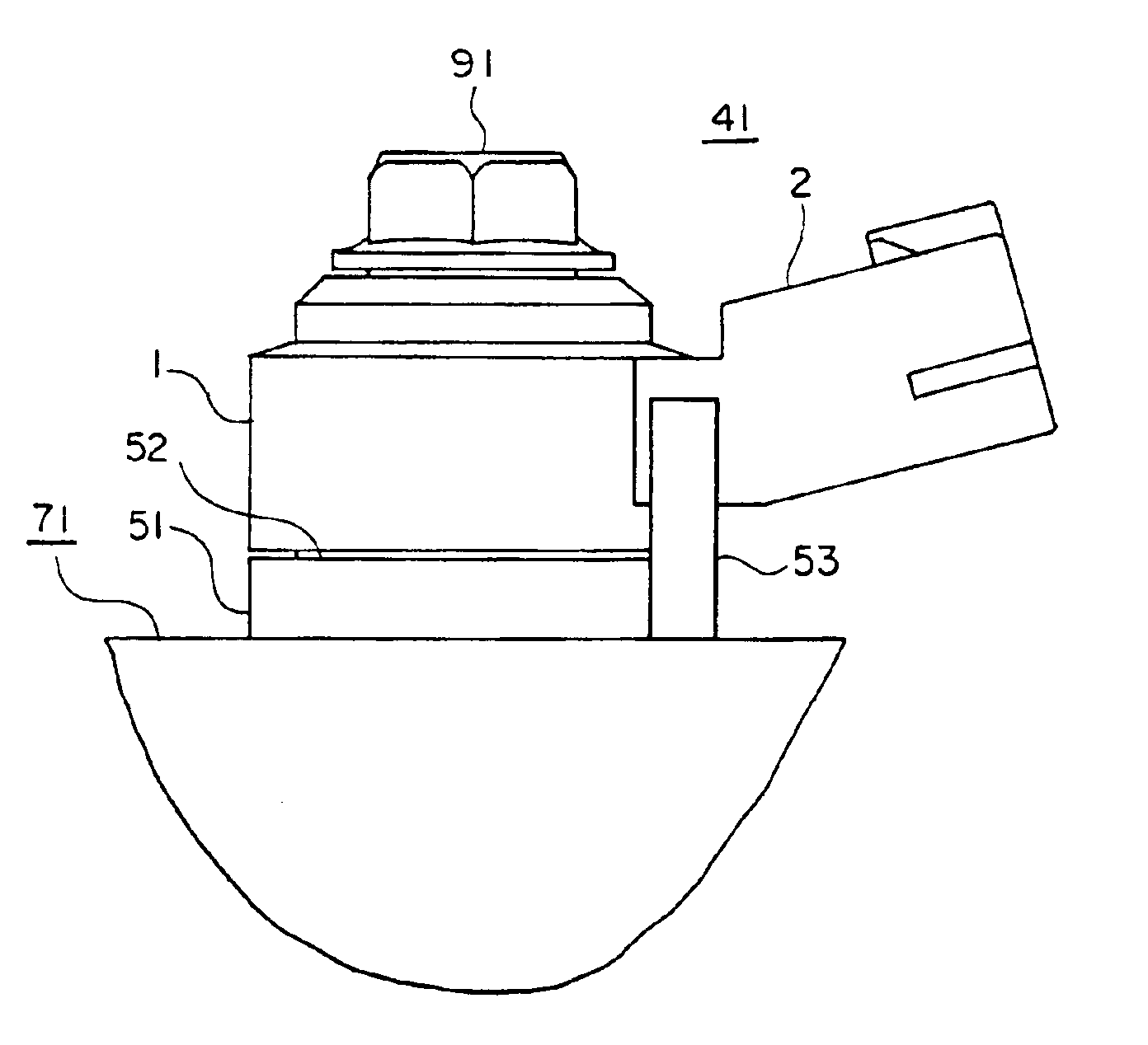
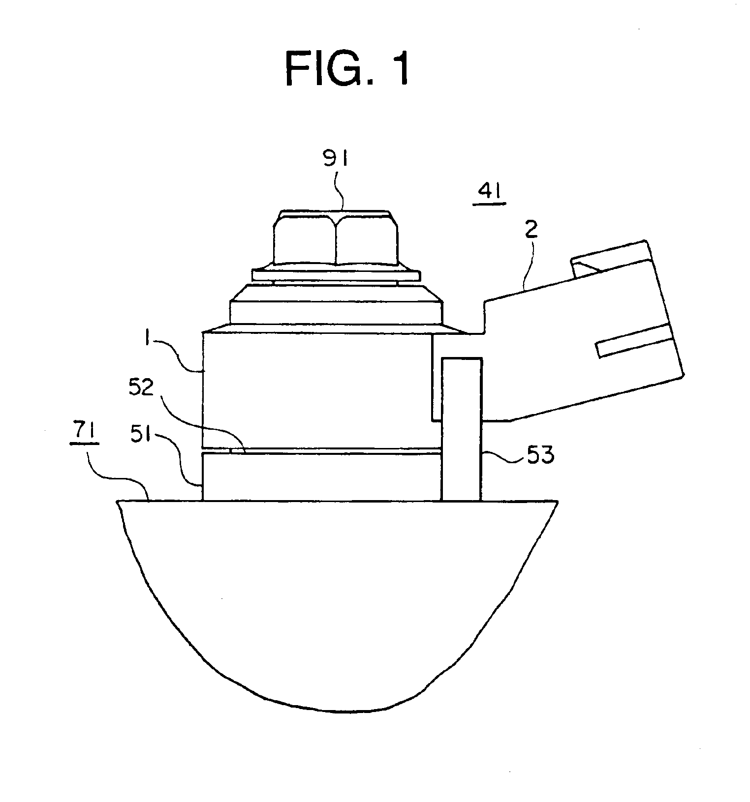
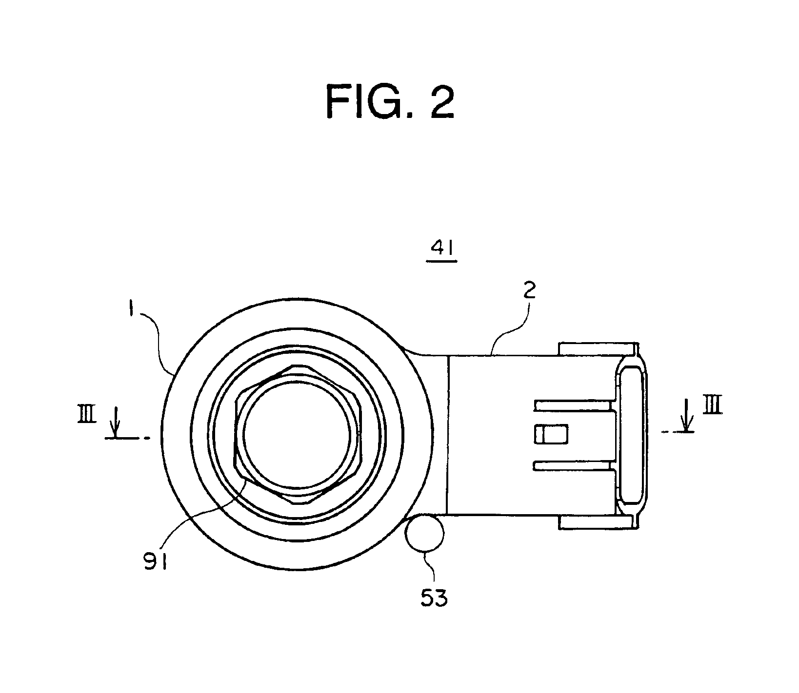
[0035]FIG. 1 is a side view showing a knock sensor for an internal combustion engine according to a first embodiment of the present invention in the state in which the knock sensor is mounted on a mounting portion of the engine in order to illustrate a mounting structure of the knock sensor. FIG. 2 is a top plan view of the knock sensor mounted on the mounting portion formed on the engine. FIG. 3 is a sectional view taken along a line III—III shown in FIG. 2 as viewed in the direction indicated by attached arrows. In the following, description will be made of the knock sensor destined to be mounted on the internal combustion engine hereinafter also referred to simply as the engine and a mounting structure of the knock sensor by reference to FIGS. 1 to 3 while referring primarily to FIG. 3. The engine knock sensor (i.e., knock sensor for the internal combustion engine)(hereinafter also referred to simply as the knock sensor) denoted generally by reference numeral 41 is comprised of a...

embodiment 2

[0046]FIG. 7 is a side view showing a knock sensor for an internal combustion engine according to a second embodiment of the present invention in the state in which the knock sensor is mounted on a mounting portion of the engine for illustrating a mounting structure of the knock sensor. FIG. 8 is a top plan view of the knock sensor shown in FIG. 7, which is mounted on the engine-side mounting portion. In an engine knock sensor 42 according to the instant embodiment of the invention, a bearing projection 17 constituting the sensor-side bearing portion is provided on the outer lateral surface of the sensor main body 1 essentially in diametrical opposition to the connector portion 2, projecting substantially orthogonally relative to the lateral surface. The bearing projection 17 can be formed simultaneously with the injection molding of the armoring resin body 15.

[0047]On the other hand, in a mounting portion designated by reference numeral 72, an erect engaging stud 54 serving as the ...

embodiment 3

[0051]FIG. 9 is a vertical sectional view showing an engine knock sensor mounting structure according to a third embodiment of the invention in the state in which the knock sensor is mounted on a mounting portion of the internal combustion engine. FIG. 10 is a top plan view showing the mounting portion of the engine knock sensor shown in FIG. 9. In the case of the knock sensor 43 according to the instant embodiment of the invention, the sensor-side bearing portion is implemented in the form of a lower resin projection 19 formed by a portion of the armoring resin body 15 projecting downwardly toward the internal combustion engine. Parenthetically, the lower resin projection 19 may be formed simultaneously with the injection molding of the armoring resin body 15.

[0052]On the other hand, in a mounting portion (engine-side knock sensor mounting portion) 73 according to the instant embodiment of the invention, the engine-side engaging portion is shaped in the form of a planar outer perip...


PUM


Abstract

Structure for mounting a knock sensor (41) on an engine includes the sensor (41) comprised of an annular main body (1) and an external connecting portion (2). The knock sensor (41) is secured onto a mounting seat (52) formed on the engine for detecting vibration thereof transmitted to a piezoelectric element (10) from the mounting seat (52) through the main cylindrical metal member (3). The mounting structure includes a clamping member (91) extending through a through-hole (5) for fixing the main body (1) on the seat (52), an engine-side engaging portion (53) radially distanced from the axis of the clamping member (91) and a bearing portion (2) provided on the sensor (41) and adapted to engage with the engine-side engaging portion (53). The knock sensor can be mounted easily with harness layout design being facilitated because the knock sensor is prevented from rotation upon mounting thereof.

Description

BACKGROUND OF THE INVENTION[0001]1. Field of the Invention[0002]The present invention relates generally a knock sensor for an internal combustion engine (hereinafter also referred to simply as the engine knock sensor) which incorporates therein a piezoelectric element and is adapted to be fixedly secured on a mounting seat formed in the internal combustion engine for the purpose of detecting vibration of the engine transmitted by way of the mounting seat. More particularly, the present invention is concerned with an engine knock sensor which includes an annular sensor main body and an external connecting portion provided on an outer peripheral surface of the sensor main body and which is designed to be fixedly secured on the mounting seat of the internal combustion engine by means of a clamping member which extends through the sensor main body. Further, the present invention is concerned with a mounting structure for mounting the engine knock sensor.[0003]2. Description of Related A...

Claims


Application Information

Patent Timeline
IPC IPC(8): G01L23/22F02D35/00F02P5/152G01H1/00G01H11/08G01H17/00G01M1/14G01P15/09G10K11/00
CPCG01H1/00G10K11/004G01P15/0907G01L23/222G01H11/08
Inventor YOKOI, AKITO
Owner MITSUBISHI ELECTRIC CORP
Why Eureka
Try Eureka