Endoscopic method for forming an artificial valve
a technology of artificial valves and endoscopes, applied in the field of endoscopes and artificial valve formation methods, can solve the problems of insufficient flexibility of treatment, difficult for the rotatable grasper to hold and suspend, and the valve formed in this application is not large and thick enough to prevent reflux, so as to achieve effective prevention of gastroesophageal reflux
- Summary
- Abstract
- Description
- Claims
- Application Information
AI Technical Summary
Benefits of technology
Problems solved by technology
Method used
Image
Examples
first embodiment
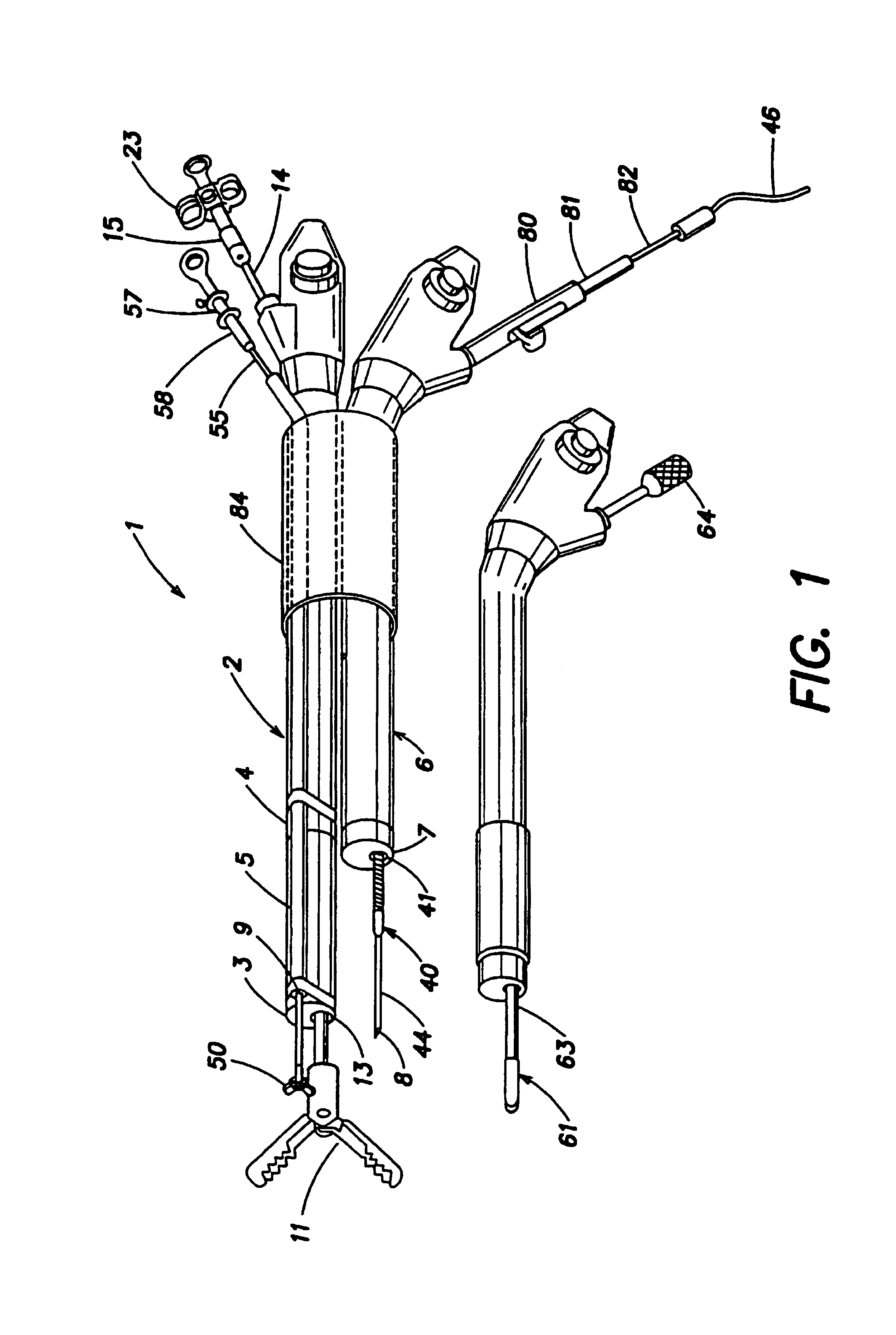
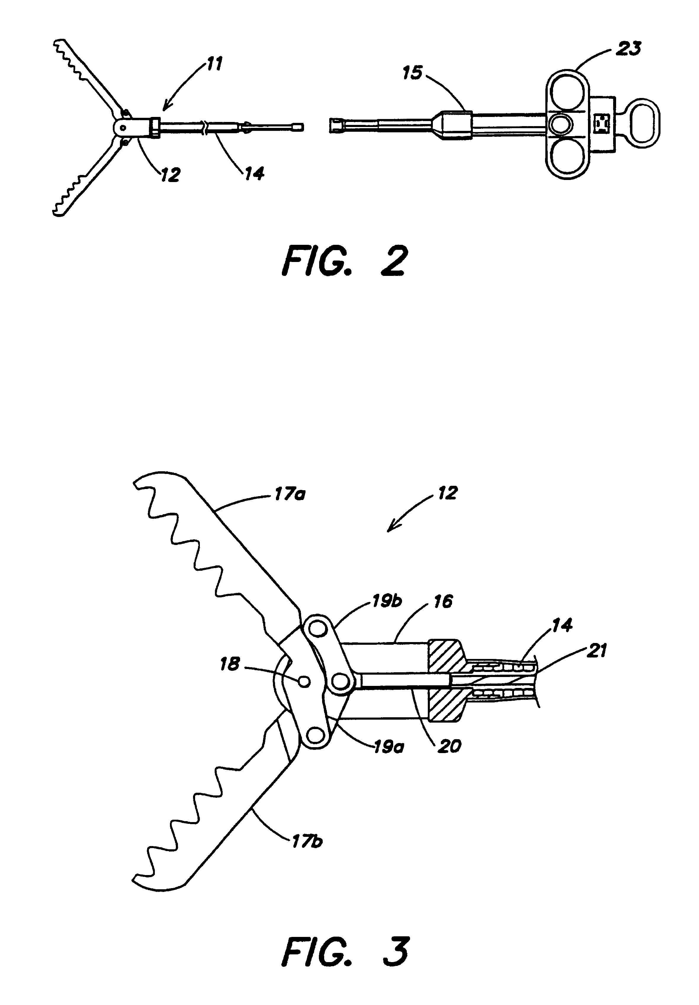
[0038]FIGS. 2 to 6 depict the first endoscope 2 and holding device 11 of the The holding device 11 comprise a distal portion 12, a sheath 14 fixed at the proximal end of the distal portion 12 and inserted in a channel 13 of the endoscope 2, and an manipulation section 15 fixed detachably at the proximal end of the sheath 14 for operating the distal portion 12. In the distal portion 12, a pair of jaws 17a and 17b, which may be forcep jaws, are fixed pivotally with a pin 18 to a cover 16 and via links 19a and 19b to a cable anchor 20. A cable 21 is fixed to the cable anchor 20, and inserted in the sheath 14. The cable 21 is fixed detachably to a sliding part 22 of the manipulation section 15. A slider handle 23 is fixed to the sliding part 22, and is translated lengthwise in relation to the manipulation section 15.
[0039]The distal portion 12 has a larger outside diameter than the channel 13 of the first endoscope 2. The jaws 17a and 17b have a plurality of teeth 24a and 24b for grasp...
second embodiment
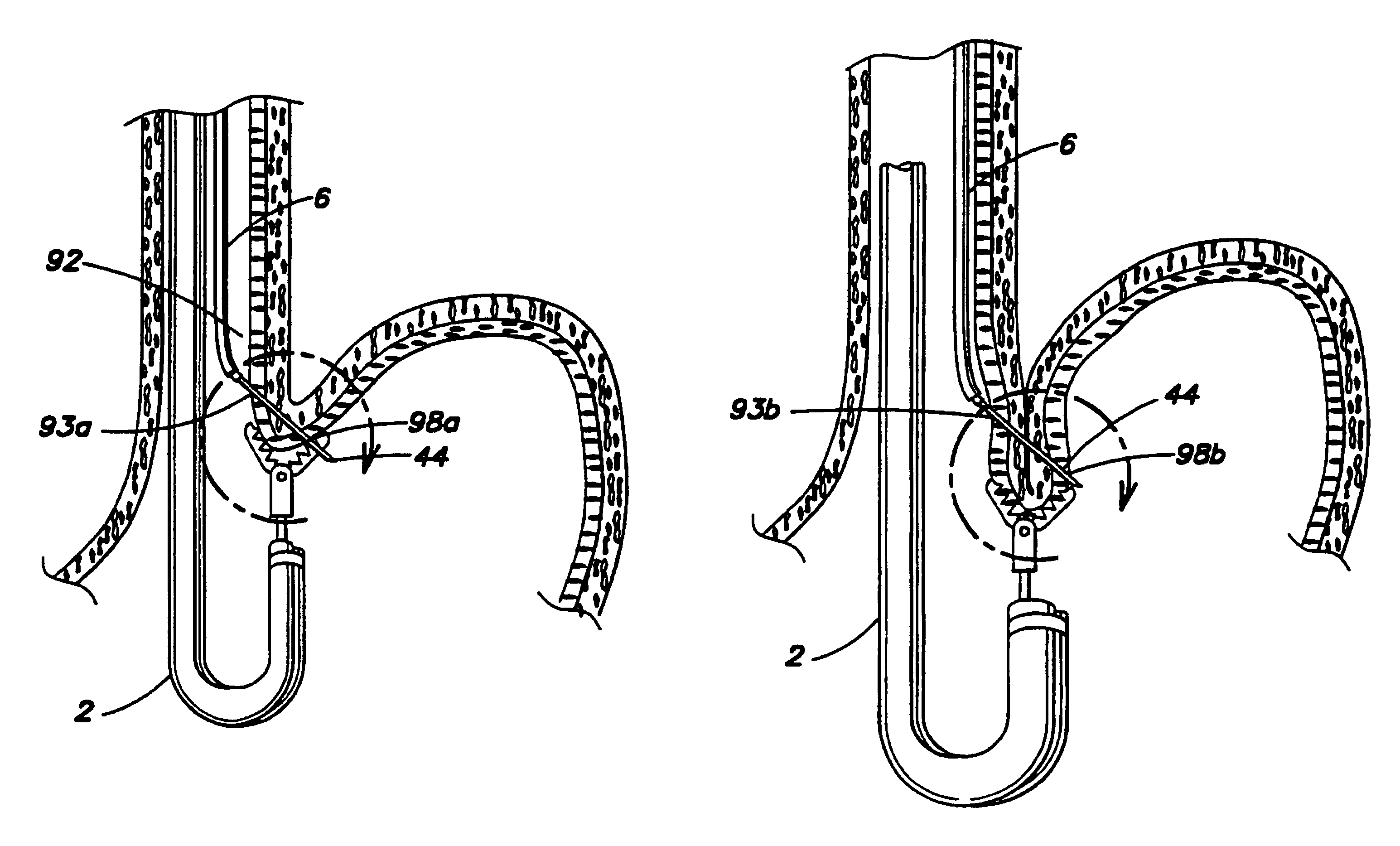
[0066]In the second embodiment, a needle tool 110 is composed as follows. Two sheaths 111a and 111b are fixed at the distal ends 112a and 112b parallel to the distal end 113 of the second endoscope 6. The sheaths 111a and 111b are fixed at the proximal portion on the outer periphery of the second endoscope 6 using medical tape at several points. The two sheaths 111a and 111b are fixed to the manipulation section 114 and accommodate needles 115a and 115b, which slide inside. Grips 116a and 116b are fixed to the proximal ends of the needles 115a and 115b and connected to connecting section 117 which is detachable.
[0067]After the first endoscope 2 or the holding device 11 holds and suspends the tissue 91, the endoscope 6 and the needle tool 110 fixed to the endoscope 6 are inserted into the body cavity of a patient. The endoscope 6 is operated to bring the distal ends of the sheaths 111a and 111b to contact with the entering points 93a and 93b and press the grips 116a and 116b to pierc...
third embodiment
[0071]In the third embodiment, a needle 120 does not have a lumen. Instead, a suture 121 is inserted and fixed in a through hole 122 of the needle 120.
[0072]The needle 120 pierces the tissue with the suture 121 inserted and fixed in the through hole 122. The suture grasping forceps 50 pulls the suture 121 out of the through hole 122 and removed through the guide 5 out of the body.
[0073]In addition to the effect of the first embodiment, because it is not necessary to insert the suture 121 in the needle, the needle 120 is thinner than the hollow needle 44 in the first embodiment. The needle 120 can be tapered to have a sharp tip, which pierces the tissue with smaller force to improve operability.
[0074]FIGS. 32 to 36 depict the fourth embodiment of the present invention. The same components as the first embodiment are indicated by the same numbers, and their description will be omitted.
[0075]In the forth embodiment, an endoscope 140 has an optical system capable of viewing in the side ...
PUM
 Abstract
Description
Claims
Application Information
 - R&D
- Intellectual Property
- Life Sciences
- Materials
- Tech Scout
- Unparalleled Data Quality
- Higher Quality Content
- 60% Fewer Hallucinations
Browse by: Latest US Patents, China's latest patents, Technical Efficacy Thesaurus, Application Domain, Technology Topic, Popular Technical Reports.
© 2025 PatSnap. All rights reserved.Legal|Privacy policy|Modern Slavery Act Transparency Statement|Sitemap|About US| Contact US: help@patsnap.com


