Desiccant bottle cap

a bottle cap and desiccant technology, applied in the field of bottles, can solve the problems of increased humidity in the bottle, eventual deterioration of the contents, and the danger of the consumer inadvertently taking desiccant pills or capsules, and achieve the effect of not affecting the efficiency of the medicine disposed therein

Inactive Publication Date: 2006-01-17
BRUNK S FRED
View PDF39 Cites 50 Cited by
  • Summary
  • Abstract
  • Description
  • Claims
  • Application Information

AI Technical Summary

Benefits of technology

[0013]The desiccant bottle cap of the present invention relates to a cap structure having a desiccant material or a desiccant containing packet adhered thereto. The desiccant bottle cap is preferably used to cover a medicine bottle so that the efficiency of the medicine disposed therein will not be impaired by moisture resulting, viz., from humid air entering the bottle. In one embodiment, the desiccant bottle cap includes a bottle cap and a desiccant packet affixed to an interior surface thereof. In another embodiment, the desiccant bottle cap includes a bottle cap, a bottle cap liner adhered to an interior surface of the bottle cap, and a desiccant packet adhered to a top surface of the desiccant liner. In yet another embodiment, loose desiccant material or a disk of desiccant material is sandwiched between a bottle cap liner and a porous material to create a bottle cap insert for removable insertion into a bottle cap.

Problems solved by technology

This results in an increase in humidity within the bottle and eventual deterioration of the contents.
However, the danger always exists that the consumer may inadvertently remove or even take the desiccant pill or capsule.
Since these desiccants often contain a cobalt salt to indicate exposure to humid atmospheres, ingestion of such materials can result in discomfort or serious illness.
Such structures have not been accepted by the drug and chemical packaging houses because they involve the use of caps of extra size or shape.
Their use would entail considerable expense and trouble in adapting present machinery to accommodate them and in making and handling cartons in which the bottles of packaged material are packed.
The inconvenience of such change has been so great that the present cap structures of this type have not been acceptable.

Method used


Image

  • Desiccant bottle cap
  • Desiccant bottle cap
  • Desiccant bottle cap

Examples


Embodiment Construction

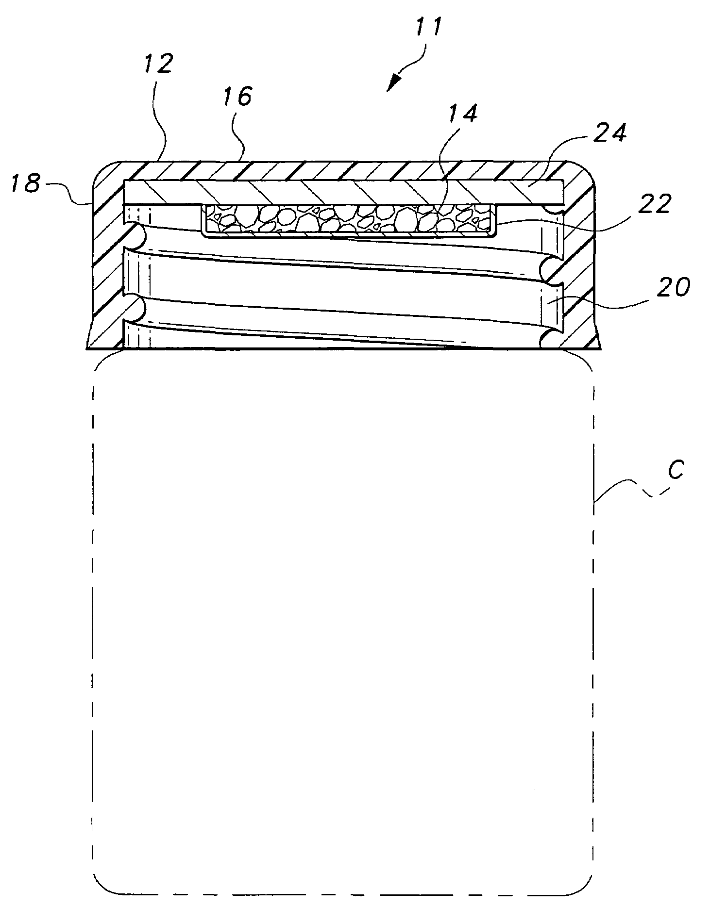
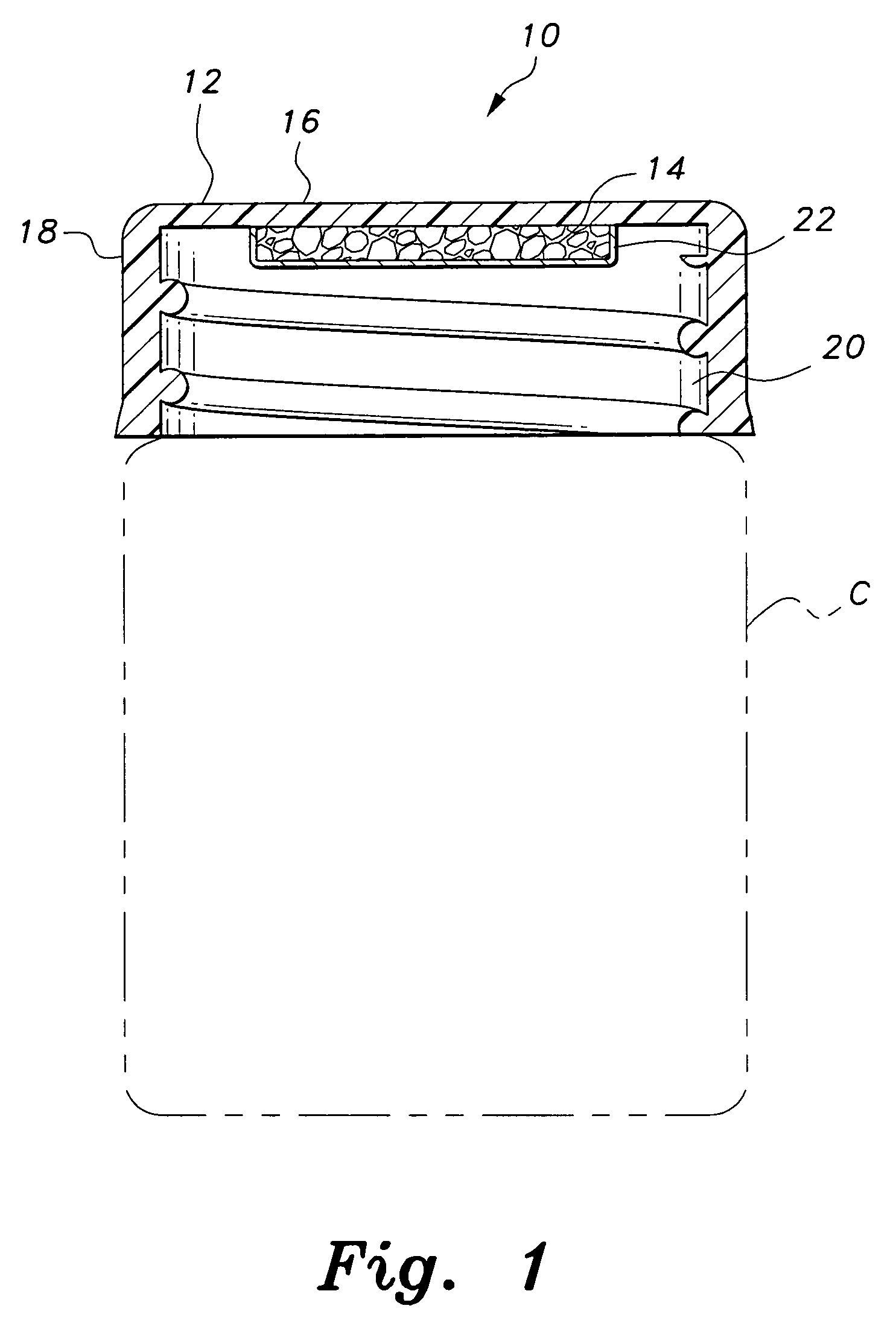
[0022]The present invention relates to a desiccant bottle cap, generally designated as 10 in the drawings, for sealing a container C and maintaining an environment relatively free from moisture within the container C. As can be seen in FIG. 1, the desiccant bottle cap 10 includes a cap structure 12 and a desiccant material 14 adhered thereto. The cap structure 12 is a cup-like member having a closed end 16, a rim 18, and a threaded interior surface 20 which engages the exterior threads around the mouth of the bottle or container C. The cap structure 12 may be made from plastic, metal or any other suitable material. While the desiccant bottle cap 10 is shown to be threaded in the drawings, suitable lugs, ribs, a childproof fastener, or other closures familiar to those skilled in the art could be used for attaching the desiccant bottle cap 10 to the container C.

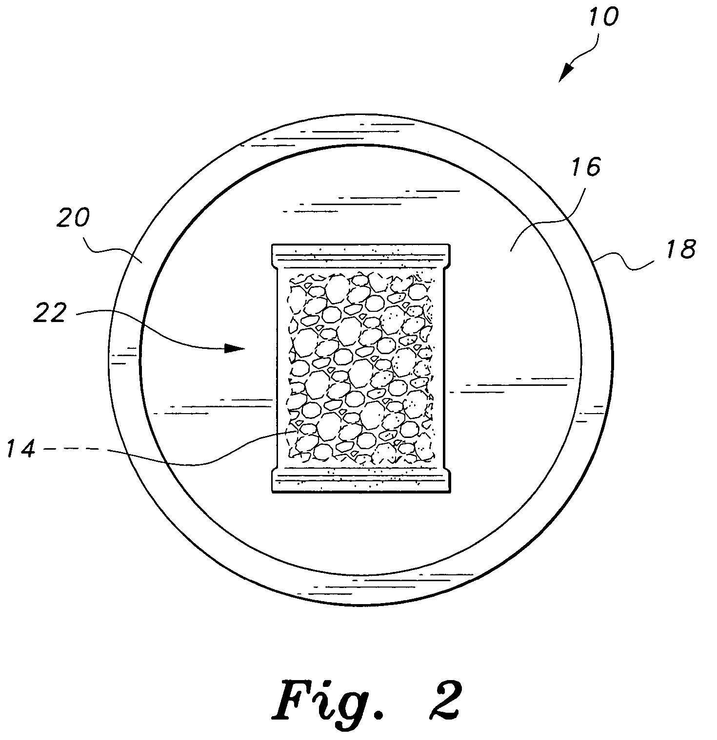
[0023]The desiccant material 14 may include silica gel or any other suitable desiccant. As is shown more clearly FIG. 2, the ...


PUM

PropertyMeasurementUnit
interior volumeaaaaaaaaaa
desiccantaaaaaaaaaa
humidityaaaaaaaaaa

Abstract

The desiccant bottle cap includes a cap structure and a desiccant material adhered thereto. The desiccant bottle cap is preferably used to cover a medicine bottle so that the efficiency of the medicine disposed therein will not be impaired by moisture resulting from humid air entering the bottle. In one embodiment, the desiccant bottle cap includes a bottle cap and a desiccant packet affixed to an interior surface thereof. In another embodiment, the desiccant bottle cap includes a bottle cap, a bottle cap liner adhered to an interior surface of the bottle cap, and a desiccant packet adhered to a top surface of the desiccant liner. In yet another embodiment, loose desiccant material or a disk of desiccant material is sandwiched between a bottle cap liner and a porous material to create a bottle cap insert for removable insertion into a bottle cap.

Description

BACKGROUND OF THE INVENTION[0001]1. Field of the Invention[0002]The present invention relates to bottle caps for medicine bottles, and more particularly, to a bottle cap having a desiccant retained therein for preventing contamination of the medicine by moisture.[0003]2. Description of the Related Art[0004]Many drugs are typically bottled in an atmosphere of very low humidity to avoid absorption of moisture within the container. However, each time the bottle is opened by the consumer for removal of a portion of the contents, atmospheric air is admitted to the container. This results in an increase in humidity within the bottle and eventual deterioration of the contents. In order to maintain a moisture-free atmosphere within the bottle after it has been opened, packagers frequently place therein a pill of desiccant material or a moisture-permeable capsule containing a desiccant. However, the danger always exists that the consumer may inadvertently remove or even take the desiccant pi...

Claims


Application Information

Patent Timeline
Patent Type & Authority Patents(United States)
IPC IPC(8): B01D53/02B01D53/26B65D81/26B01D53/04B01D59/26B03C3/00B65D39/00B65D41/00B65D43/00B65D47/00B65D51/00B65D51/30B65D53/00B65D55/02B65D85/00
CPCB01D53/0415B01D53/261B65D51/30B01D2257/80B01D2259/4533B01D2253/106
Inventor BRUNK, S. FRED
Owner BRUNK S FRED
Why Eureka
Try Eureka