Electric motor with screwless plug-type mounting

a technology of screw-type mounting and electric motor, which is applied in the direction of machines/engines, mechanical equipment, liquid fuel engines, etc., can solve the problems of direct vibration-transmitting connections, etc., and achieve the effect of reducing the emission of operating nois

Active Publication Date: 2006-01-17
EBM PAPST MULFINGEN GMBH & CO KG
View PDF16 Cites 32 Cited by
  • Summary
  • Abstract
  • Description
  • Claims
  • Application Information

AI Technical Summary

Benefits of technology

[0005]The present invention is based on the object of achieving a significant reduction in the emission of operating noises with an electric motor of the

Problems solved by technology

This means that the latching elements which are provided for forming a holding

Method used


Image

  • Electric motor with screwless plug-type mounting
  • Electric motor with screwless plug-type mounting
  • Electric motor with screwless plug-type mounting

Examples


Embodiment Construction

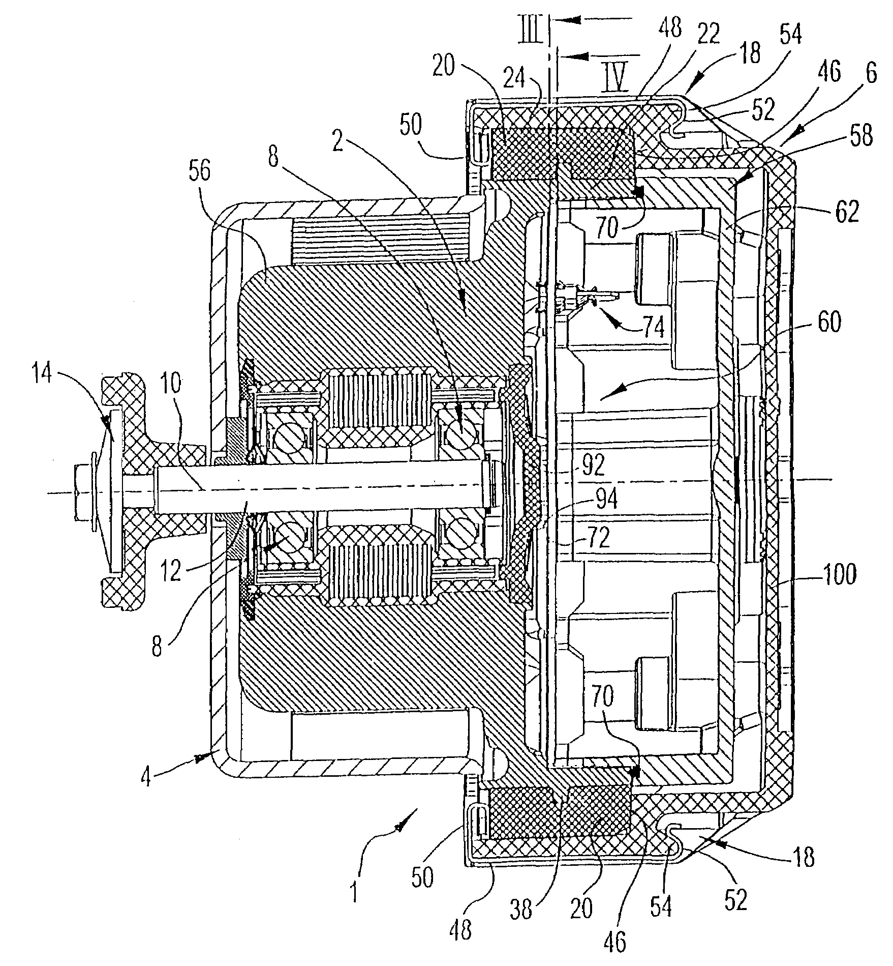
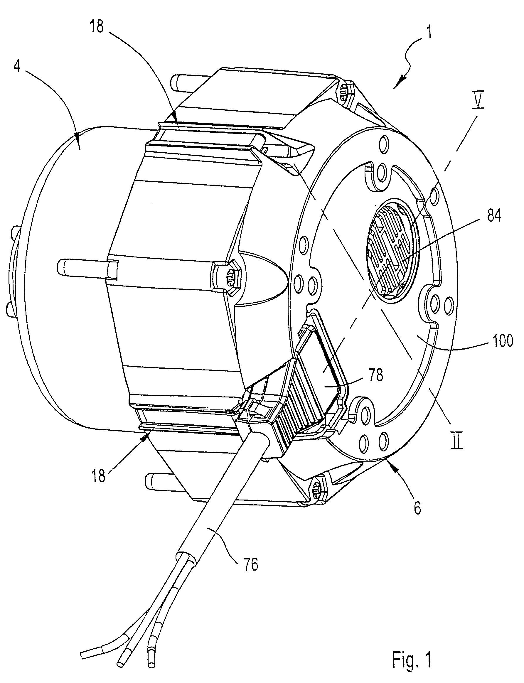
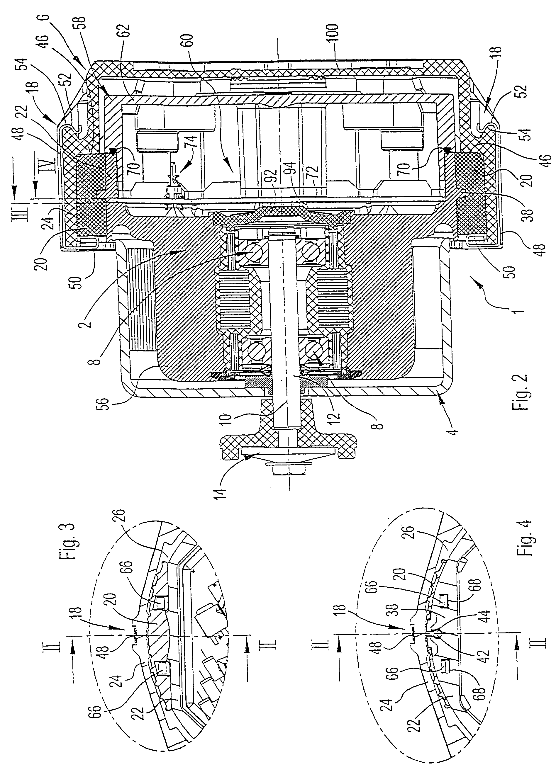
[0020]An electric motor 1 according to the invention is formed in the illustrated embodiments as an external rotor motor. Here, the electric motor 1 is composed—see in this respect in particular the exploded views in FIGS. 7 and 9—of a stator 2, a rotor (external rotor) 4 and a motor carrier 6. The rotor 4 is mounted within the stator 2 by means of rotary bearings 8 so as to be capable of rotating about an axis 10 of the motor (see in this respect in particular the longitudinal sections in FIGS. 2, 5 and 8). In the embodiment according to FIGS. 1 to 7, a rotor shaft 12 extends axially out from the rotor 4 in the forward direction and an optional attachment element 14 for connecting a part or assembly (not illustrated) to be driven is arranged at its protruding end. In the case of the alternative embodiment according to FIGS. 8 and 9, the rotor shaft 12 ends in the region of an end wall of the rotor 4, the rotor 4 being fitted directly on its outer circumference with a fan wheel 16, ...


PUM


Abstract

An electric motor, in particular an external rotor motor, comprising a stator which is attached by means of latching elements to a motor carrier using a plug-in joining operation. The elastic elements for isolating vibration are arranged in the connecting region between the stator and the motor carrier in a way that the stator is indirectly connected to the motor carrier by means of the elastic elements.

Description

CROSS REFERENCE TO RELATED APPLICATION[0001]This application claims priority to DE 102 45 971.1 filed Sep. 30, 2002, which is currently pending.BACKGROUND OF THE INVENTIONField of the Invention[0002]The present invention relates to an electric motor, in particular an external rotor motor, having a stator which is attached to a motor carrier through a screwless fastening means of latching elements using an axial plug-in joining operation.[0003]Such a motor is described comprehensively in WO 00 / 57541. For screwless mounting, the stator has axial latching arms which engage with end latching noses directly in the motor carrier or in corresponding openings in a pot-shaped housing part. Especially when the motor is used, as also described, for driving a fan wheel, in some cases extremely strong vibrations which can lead to disrupting noises occur during operation.[0004]Although measures for vibration isolation are already known in the prior art (cf. for example EP 0 240 644 B1), these usu...

Claims


Application Information

Patent Timeline
IPC IPC(8): H02K5/24F04D29/66
CPCH02K5/24F04D29/668
Inventor STRENG, GUNTERMULLER, RAINERGELBING, MARKUSFREUDENBERG, JURGENHAFNER, JOCHEN
Owner EBM PAPST MULFINGEN GMBH & CO KG
Why Eureka
Try Eureka