

Auxiliary switching circuit for a chopping converter
a technology of auxiliary switching circuit and chopping converter, which is applied in the direction of power conversion system, electric variable regulation, instruments, etc., can solve the problems of reducing the loss of the actual blockage of the diode, and the negligible loss of the turn-off switch, so as to reduce the loss
- Summary
- Abstract
- Description
- Claims
- Application Information
AI Technical Summary
Benefits of technology
Problems solved by technology
Method used
Image

Examples
Embodiment Construction
[0061]The same elements have been designated with the same references in the different drawings. For clarity, only those components which are necessary to the understanding of the present invention have been shown in the drawings and will be described hereafter. In particular, the structure of the power switch control circuit has not been detailed and is not part of the present invention, its implementation being within the abilities of those skilled in the art based on the functional indications given in the present description.
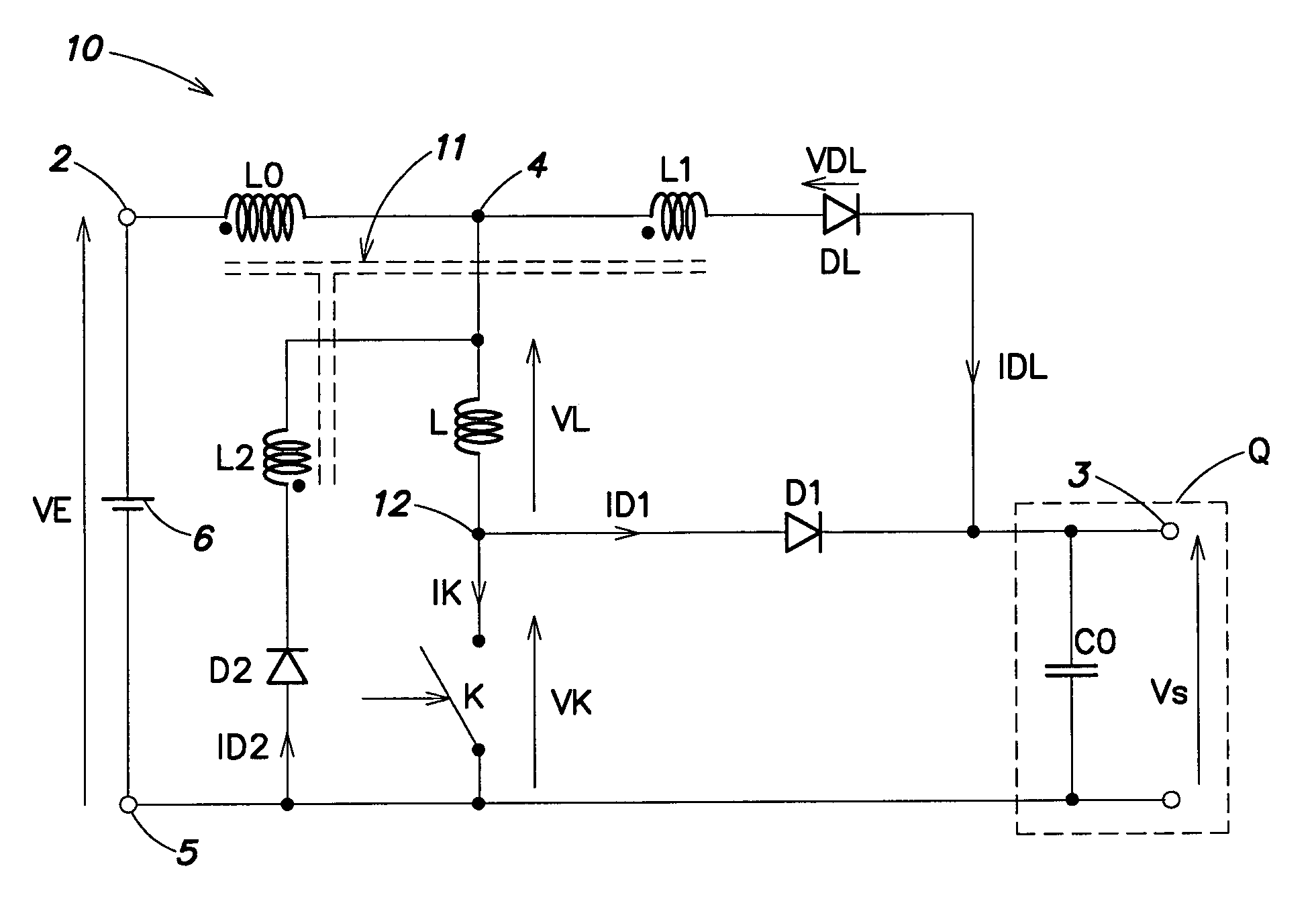
[0062]A feature of the present invention is to provide a magnetic circuit for organizing the discharge of an inductance for controlling the di / dt value, especially, upon closing of the power switch of a switched-mode converter.
[0063]Another feature of the present invention is to use this magnetic circuit to temporarily store the power generally lost upon switching of the power switch and for storing this power in the converter to the benefit of the load.
[006...
PUM
 Abstract
Description
Claims
Application Information