Electromagnetic protection test and surveillance system

a technology of electromagnetic protection and surveillance system, applied in the field of electromagnetic protection test and surveillance system, can solve the problem of relative low standing wave ratio across the entire operational frequency band, and achieve the effect of convenient space saving, convenient installation, and convenient unobtrusive suppor

Inactive Publication Date: 2006-01-17
NORTH SOUTH HLDG
View PDF2 Cites 49 Cited by
  • Summary
  • Abstract
  • Description
  • Claims
  • Application Information

AI Technical Summary

Benefits of technology

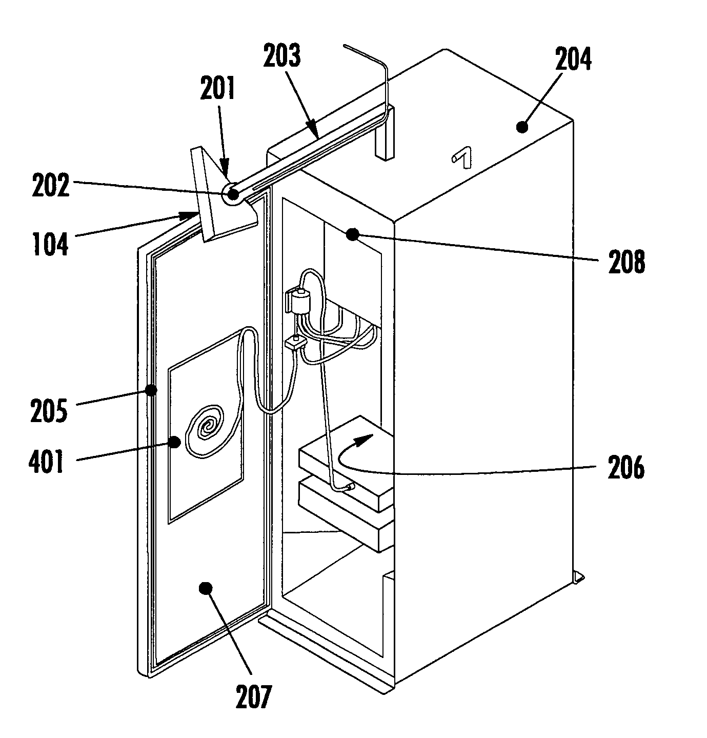
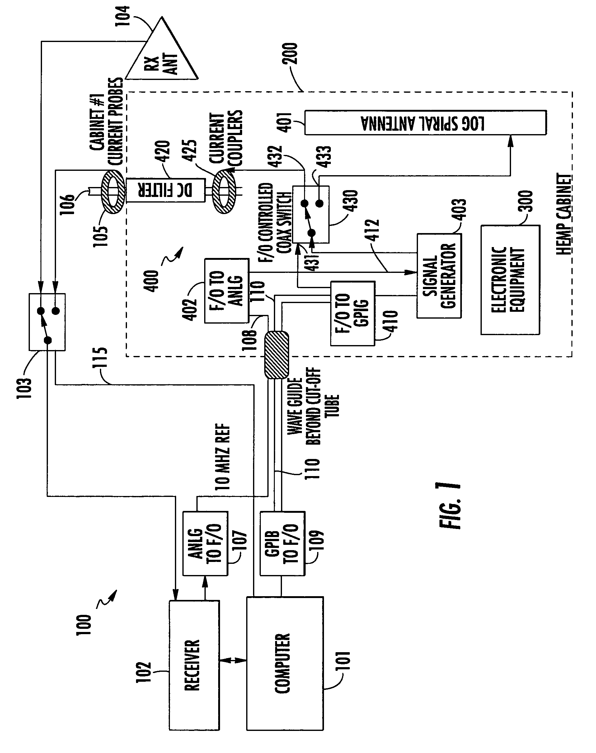
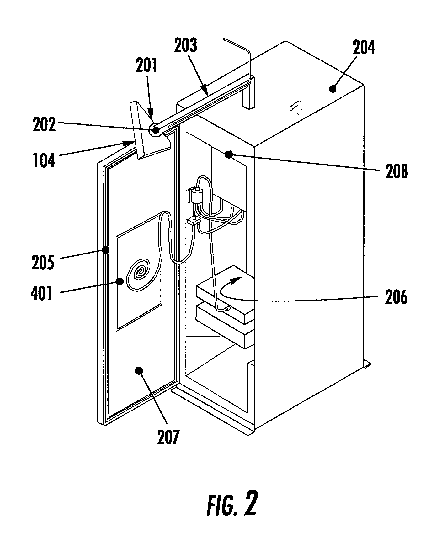
[0007]For this purpose, the architecture of the present invention includes an external subsystem, which is located outside an Electromagnetic shielded enclosure containing electronic equipment to be protected, and an internal subsystem, that is configured to be readily installed along with the electronic equipment within the shielded equipment housing proper. The external subsystem includes a host computer, which controls the operation of each of the transmit and receive subsystems, and a receiver, which is selectively coupled by the host processor to either an RF receive antenna or to a current sense probe. The receive antenna, which may be implemented as a log periodic antenna, that may be pivotally mounted by way of a boom to the cabinet, so that its boresight may be selectively directed at the center of a cabinet door-mounted, ferrite-loaded log-spiral RF transmission antenna for either of first and second spatial locations of the antenna (respectively associated with the open or closed state of a cabinet door). Configuring the RF transmission antenna as a low profile, ferrite-loaded, (log)-spiral shape facilitates its being unobtrusively supported on the inside of a cabinet door, so as to facilitate space saving, and also enable it to be located directly adjacent to the electromagnetic shielding structure of the cabinet. This serves to minimize physical interference with other user equipment, and provides an efficient radiator with constant load impedance over a wide frequency range that is substantially unaffected by conductive surfaces (the door shielding) in close proximity. The current sense probe is coupled to a power interface, through which primary power is supplied from an external power supply to the circuitry components housed within the shielding enclosure.
[0008]All control signals transmitted between external and internal subsystems are routed into the shielded cabinet by way of fiber optic links, in order to eliminate RF leakage from the shielded enclosure, and thereby prevent RF emissions that might interfere with other systems in an equipment bay commonly shared with the protected equipment. A prescribed reference signal (e.g., a 10 MHz clock internal to the receiver) is used to synchronize and lock respective receive and transmit oscillators within the receiver and signal generator, so that the two exactly track each other during scanning of test frequencies. The signal generator is operative under processor control to generate all test signals that are employed to test the effectiveness of the electromagnetic shielding of the cabinet, including the RF attenuation of a power filter that is coupled with the power source for the cabinet. Having the source of test signals and its associated transmission antenna located within the shielded cabinet serves to minimize the impact of such signals on circuits within the environment outside the cabinet.
[0009]The receive antenna is preferably mounted by way of a pivotable attachment at the distal end of a boom, which is supported by and extends outwardly from the top of the shielding enclosure. This allows the receive antenna to readily clear a cabinet door through which physical access to the interior of the cabinet is provided. In addition, the pivotable attachment of the antenna to the distal end of the boom allows the antenna to be oriented at a selected boresight projection angle relative to the plane of the log-spiral transmission antenna for either the open or closed state of the door. A 45° degree orientation of the receive antenna allows it to capture both horizontal and vertical polarization components of the RF emissions from RF transmission antenna for either of a first spatial location of antenna corresponding to the open state of the cabinet door (calibration mode), or a second spatial location of the transmission antenna corresponding to the closed state of the cabinet door (verification mode). To compensate for the effect of the ground plane imparted by the metallic material of the door, the printed circuit board upon which the spiral pattern of the transmission antenna is preferably back-loaded with ferrite material. This results in a relatively low standing wave ratio across the entirety of its operational frequency band.
[0012]Once the control processor has conducted the above routine for the last RF frequency in the RF calibration band, it proceeds to calibrate the effectiveness of the power filter. Alternatively, the control processor may calibrate the effectiveness of the power filter, prior to conducting the calibration routine, without a loss in generality. With the cabinet door(s) closed, the control processor sets the positions of signal routing switches so that the transmit / receive path proceeds from the signal generator—current coupler—the power filter—current probe—receiver.

Problems solved by technology

This results in a relatively low standing wave ratio across the entirety of its operational frequency band.

Method used


Image

  • Electromagnetic protection test and surveillance system
  • Electromagnetic protection test and surveillance system
  • Electromagnetic protection test and surveillance system

Examples


Embodiment Construction

[0024]Before describing the electromagnetic protection test and surveillance system in accordance with the present invention, it should be observed that the invention resides primarily in a modular arrangement of conventional communication electronic circuits and electronic signal processing circuits and components therefor. In a practical implementation that facilitates packaging in a hardware-efficient equipment configuration, these modular arrangements may be readily implemented as field programmable gate array (FPGA)-, or application specific integrated circuit (ASIC)-based chip sets. Consequently, the configuration of such an arrangement of circuits and components and the manner in which they are interfaced with one another have, for the most part, been illustrated in the drawings in readily understandable block diagram format, which show only those specific details that are pertinent to the present invention, so as not to obscure the disclosure with details which will be readi...


PUM


Abstract

A test architecture performs calibration and site verification testing of the effectiveness of a radiation shielding structure within which electronic equipment is housed. An external subsystem is outside a shielding cabinet, and an internal subsystem resides with the electronic equipment within the shielded equipment housing proper. The external subsystem includes a host computer, which controls the operation of transmit and receive subsystems. An external receiver is selectively coupled by the host processor to either an RF receive antenna or to a current sense probe. All control signals from the external subsystem are conveyed into the shielded cabinet by way of fiber optic links, in order to preserve the shielding effectiveness of the cabinet. Having the source of test signals and its associated transmission antenna located within the shielded cabinet serves to minimize the impact of such signals on circuits within the environment outside the cabinet.

Description

[0001]The present invention was made with Government support under Prime Contract No. HQ0006-01-C-0001 awarded by the Department of Defense. The Government has certain rights in this invention.FIELD OF THE INVENTION[0002]The present invention relates in general to communication systems and subsystems therefor, and is particularly directed to a new and improved architecture and methodology for performing calibration and installation site verification testing of the effectiveness of an electromagnetic radiation shielding structure within which electronic equipment is installed.BACKGROUND OF THE INVENTION[0003]In order to protect the circuit components of electronic equipment from potentially damaging electromagnetic radiation, such as an externally-sourced electromagnetic pulse (EMP) or other interference signals such as radar, broadcast radio and TV, Cellular Phone, etc., it is customary practice to house the equipment within some form of shielded structure such as a cabinet, or encl...

Claims


Application Information

Patent Timeline
Patent Type & Authority Patents(United States)
IPC IPC(8): G01R27/28
CPCG01R29/0835
Inventor HERNANDEZ, ARECIO A.HOYT, DAVID GEORGE
Owner NORTH SOUTH HLDG
Why Eureka
Try Eureka