Vibrating screen with a loading pan

a technology of vibrating screen and loading pan, which is applied in the direction of solid separation, chemistry apparatus and processes, botany apparatus and processes, etc., can solve the problems of deterioration of control devices and moving parts, the same drawback, so as to reduce the collapsing of springs in use, the effect of low production cost and low price of sal

Inactive Publication Date: 2006-01-24
MACNAUGHTON DOUGLAS J
View PDF27 Cites 23 Cited by
  • Summary
  • Abstract
  • Description
  • Claims
  • Application Information

AI Technical Summary

Benefits of technology

[0010]In accordance with another aspect of the present invention, the loading pan is wider than the screen box. More specifically, the loading pan is about 60% wider than the screen box. The loading pan has a plated bottom surface and sloped sides forming a funnel on the upper end of the screen box. In use, the sloped sides retain about 30% or more of a load of screenable material in the loading pan until most of the central portion of the load has been moved over to the top screen. The flow of screenable material from the loading pan to the top screen is thereby more uniform.
[0011]In yet another aspect of the present invention, each of the first and second pairs of springs have torsion bushings therein, and a pair of arms joining the torsion bushings and forming an acute angle pointing toward the lower end of the screen box. The top arm in each spring makes an angle with the horizontal plane, which is greater than the inclination of the screen box. Because of this characteristic, the friction forces caused by a load of screenable material in the loading pan produce a torque on each spring in a direction opposite a vertical loading on each spring, to reduce a collapsing of the springs in use.
[0012]Still another feature of the vibrating screen of the present invention is that it is susceptible of a low cost of manufacture with regard to both materials and labour, and which accordingly is then susceptible of low prices of sale to the consumer, thereby making such vibrating screen economically available to the public.

Problems solved by technology

When a load of gravel is dropped all at once in the upper end of a common vibrating screen, the upper springs become compressed, thereby collapsing the upper half of the screen box for a few seconds.
Most small portable vibrating screens of the prior art have this type of spring arrangement and suffer from the same drawback.
These control devices and moving parts are subject to deterioration from dust and shocks associated with the environment in which a vibrating screen operates.

Method used


Image

  • Vibrating screen with a loading pan
  • Vibrating screen with a loading pan
  • Vibrating screen with a loading pan

Examples


Embodiment Construction

[0024]While this invention is susceptible of embodiment in many different forms, there is shown in the drawings and will be described in details herein one specific embodiment, with the understanding that the present disclosure is to be considered as an example of the principles of the invention and is not intended to limit the invention to the embodiment illustrated and described.

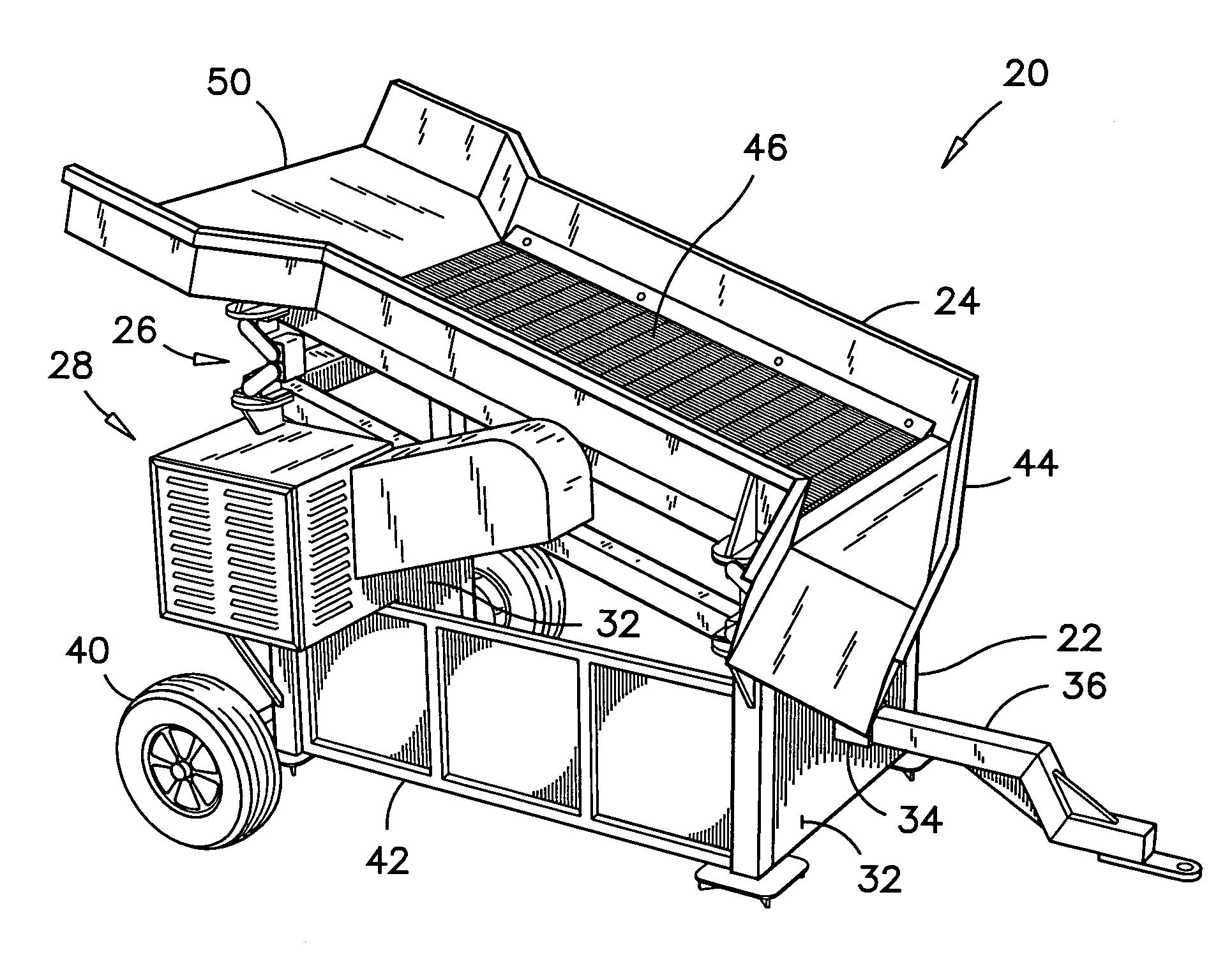
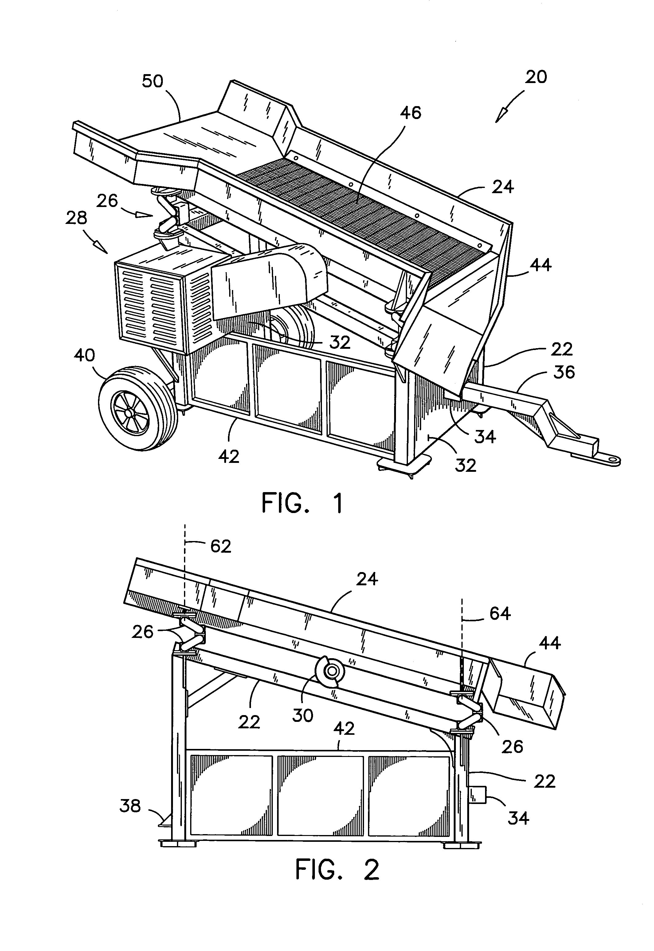
[0025]Referring to FIGS. 1 and 2, the vibrating screen 20 according to the preferred embodiment is described herein below in a general form. The preferred vibrating screen 20 has an arched frame 22 supporting a screen box 24 on four springs 26 affixed to the top of the frame 22. An engine 28 drives an eccentric shaft 30 affixed to the screen box 24, to impart a vibrating movement to the screen box 24.

[0026]The preferred springs 26 are of the type known as oscillating mountings, manufactured by ROSTA-WERK AG, a company from Switzerland having distributors throughout the world. Each spring 26 is characterize...


PUM


Abstract

The vibrating screen has a frame, a screen box, two pairs of springs supporting the screen box over the frame and a driven eccentric shaft mounted under the screen box. The vibrating screen is characterized by a loading pan affixed to the upper end of the screen box. The loading pan has a central region over the upper springs such that a flexion of the structural members under the loading pan is minimum. The loading pan is wider than the screen box and has sloped sides forming a funnel on the upper end of the screen box to retain the side portions of a load until most of the central portion has been moved to the screen box. In another aspect, each spring has torsion bushings therein, with a pair of arms joining the torsion bushings and forming an angle pointing toward the lower end of the screen box.

Description

FIELD OF THE INVENTION[0001]This invention pertains to vibrating screens for screening gravel, top soil, and the like, and more particularly, it pertains to a vibrating screen having a loading pan thereon for receiving loads of screenable material from a bucket loader and for controlling the flow of these loads to the screen box.BACKGROUND OF THE INVENTION[0002]Small and portable vibrating screens are used for examples, by landscape contractors, gardeners, farmers, and excavation and trucking companies. These vibrating screens are usually loaded by small Skid-Steer™ loaders or other similar front-end bucket loaders. This type of small portable vibrating screens is illustrated and described in Applicant's U.S. Pat. No. 5,899,340 issued on May 4, 1999.[0003]When a load of gravel is dropped all at once in the upper end of a common vibrating screen, the upper springs become compressed, thereby collapsing the upper half of the screen box for a few seconds. During that period, the amplitu...

Claims


Application Information

Patent Timeline
Patent Type & Authority Patents(United States)
IPC IPC(8): B07B1/28B07B1/00B07B1/46
CPCB07B1/46B07B1/005
Inventor MACNAUGHTON, DOUGLAS J.
Owner MACNAUGHTON DOUGLAS J
Why Eureka
Try Eureka