
Methods and apparatuses to identify devices

a technology of identifying devices and methods, applied in the field of devices having an identifier, can solve problems such as requiring considerable logic, extending the range of the reading system, and corrupting each other

Inactive Publication Date: 2006-01-24
RUIZHANG TECH LTD CO
View PDF58 Cites 116 Cited by
  • Summary
  • Abstract
  • Description
  • Claims
  • Application Information

AI Technical Summary

Benefits of technology

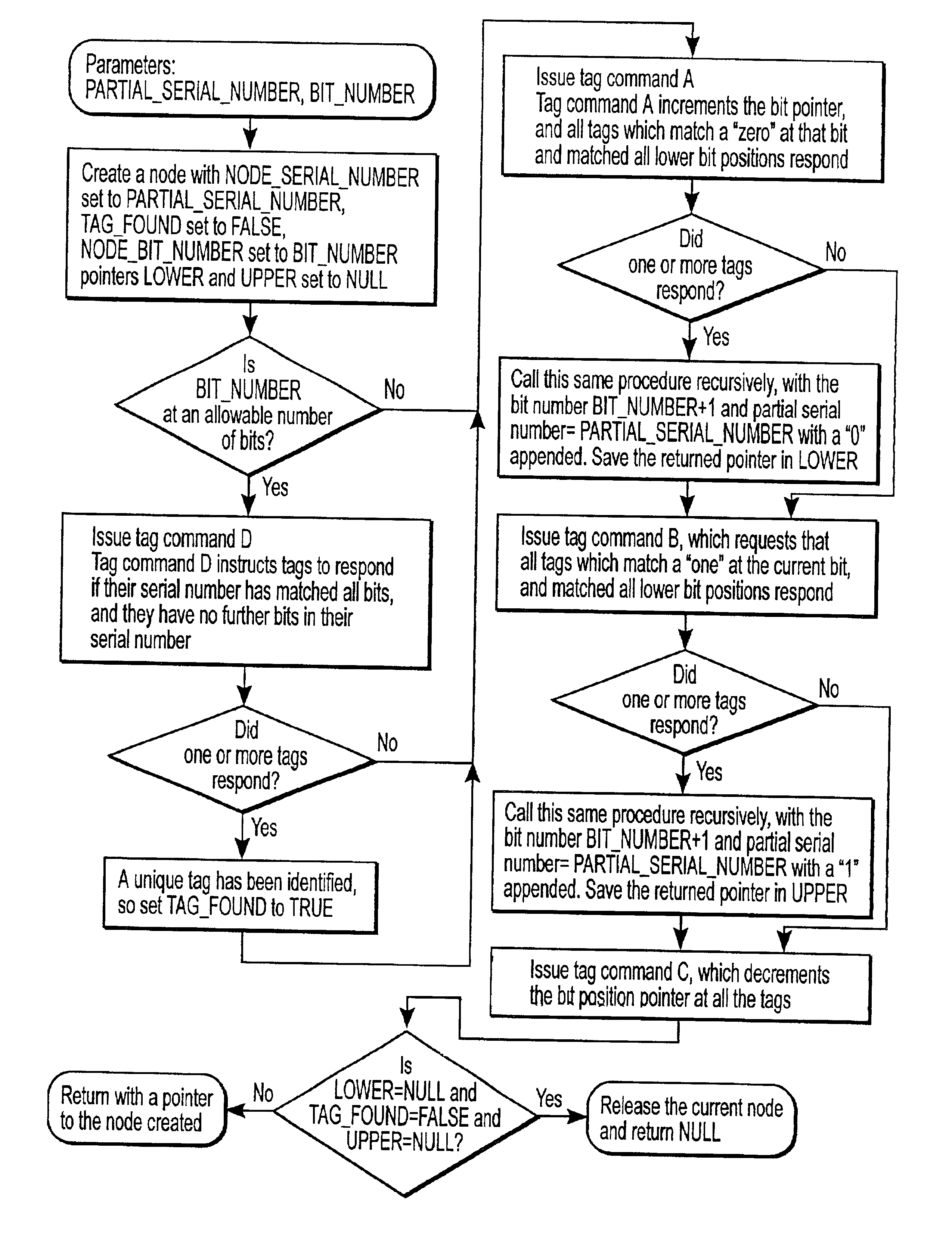
This approach enables longer read ranges for RF tags with reduced complexity and cost, allowing for accurate identification of multiple tags without collision issues, using a binary search protocol to ensure unique responses from each tag.

Problems solved by technology

Two problems often occur when extending the range of the reading system.
One of the problems is that there is limited power available for transmission from the wireless tag, and if the range is significant, it is possible that many tags will be within the range of the interrogating system and their replies may corrupt each other.
Current implementations of radio frequency (RF) tags require considerable logic to handle interface protocol and anti-collision problems which occur when multiple tags within the range of a reader attempt to all reply to an interrogating message.
This considerable size required by an integrated circuit increases the cost of the RF tag and thus makes is less likely for such a tag to be more commonly used.
However, these prior art approaches provide inefficient solutions for avoiding collision when reading multiple RF tags.

Method used


Image

  • Methods and apparatuses to identify devices
  • Methods and apparatuses to identify devices
  • Methods and apparatuses to identify devices

Examples


Embodiment Construction

[0023]The subject invention will be described with reference to numerous details set forth below, and the accompanying drawings will illustrate the invention. The following description and drawings are illustrative of the invention and are not to be construed as limiting the invention. Numerous specific details are described to provide a thorough understanding of the present invention. However, in certain instances, well known or conventional details are not described in order to not unnecessarily obscure the present invention in detail.

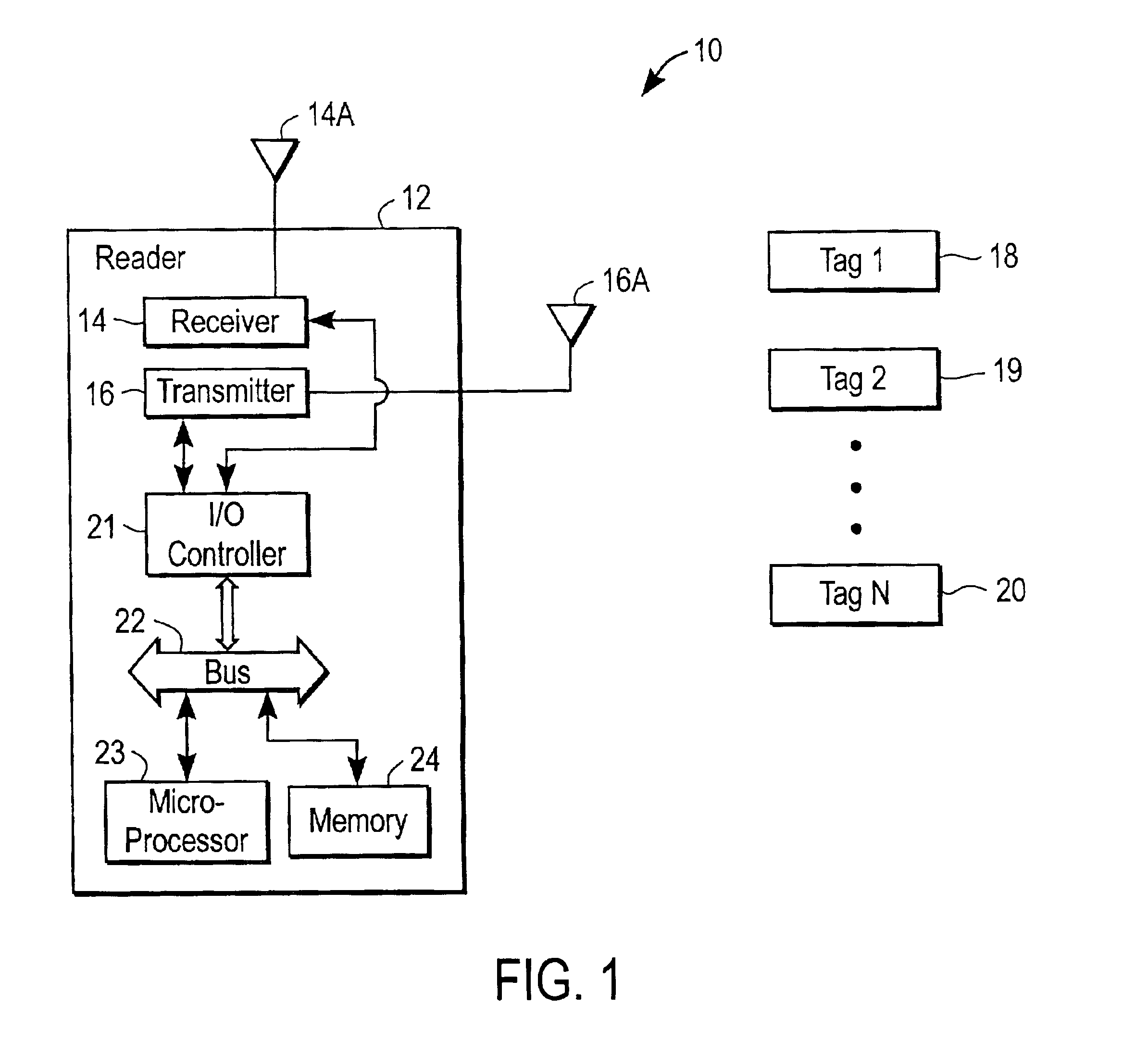
[0024]FIG. 1 illustrates an example of an identification system 10 which includes a reader 12 and a plurality of tags 18, 19, and 20. The system is typically a reader-talks-first RF ID system using either passive or semi-passive active backscatter transponders as tags. The incorporation of a battery and / or memory into a tag is an expanded feature to facilitate longer read range; however, the use of the battery does require certain trade-offs, such as...


PUM


Abstract

A reader identifies tags without requiring or determining whether a response to an interrogation was a single response from a single tag or multiple responses from multiple tags. A method is performed by a tag in an identification system, and the method includes receiving a first data from a reader, and correlating the first data with a first corresponding portion of the tag's identification code, and specifying a match if the first data matches the first corresponding portion, and receiving second data which, combined with the first data, is correlated with a second corresponding portion of th tag's identification code.

Description

[0001]This application hereby claims the benefit of two prior U.S. Provisional Patent Applications: (1) application Ser. No. 60 / 295,502, filed May 31, 2001, and (2) application Ser. No. 60 / 329,391, filed Oct. 12, 2001.BACKGROUND OF THE INVENTION[0002]The present invention relates to the field of devices having an identifier, such as tags, and further relates to methods and apparatuses for identifying such tags.[0003]It is desirable to interrogate multiple wireless tags by sending from an interrogating transmitter a code and having information transmitted by the tag in response. This is commonly accomplished by having the tag listen for an interrogation message and for it to respond with a unique serial number and / or other information. However, it is desirable to extend the range of wireless tags so that it is not necessary to bring each tag close to a reader for reading. Two problems often occur when extending the range of the reading system. One of the problems is that there is lim...

Claims


Application Information

Patent Timeline
Patent Type & Authority Patents(United States)
IPC IPC(8): G06K19/06G06K7/00G06K7/08
CPCG06K7/0008G06K7/10049G06K7/08
Inventor STEWART, ROGER G.SMITH, JOHN STEPHEN
Owner RUIZHANG TECH LTD CO
Learn More