Bearing insert with controlled endplay

a technology of endplay and bearing, which is applied in the direction of bearings, rigid supports of bearing units, mechanical devices, etc., can solve the problems of increasing wear, affecting the quality of bearings, and affecting the performance of bearings, and increasing the wear of bearings,

Inactive Publication Date: 2006-01-24
BALDOR ELECTRIC COMPANY
View PDF10 Cites 36 Cited by
  • Summary
  • Abstract
  • Description
  • Claims
  • Application Information

AI Technical Summary

Problems solved by technology

In certain known arrangements, the foregoing structures are incapable of accommodating system expansion or misalignment, thereby increasing the wear and eventually damaging a bearing assembly, a tapered sleeve, and other associated components of the system.
Existing mounting components also can be expensive to manufacture and difficult to assembly and disassemble.

Method used


Image

  • Bearing insert with controlled endplay
  • Bearing insert with controlled endplay
  • Bearing insert with controlled endplay

Examples


Embodiment Construction

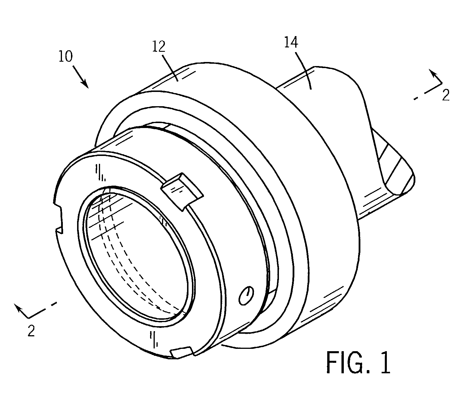
[0018]Turning now to the drawings, and referring first to FIG. 1, a bearing system 10 is illustrated generally for securing a mechanical member within a hollow member. In the application illustrated in FIG. 1, the hollow member is part of a bearing assembly 12 secured on a shaft 14. As will be appreciated by those skilled in the art, many such applications exist, typically for rotating machinery and power transmission applications. As noted above, it should be borne in mind that the system described herein may be applied in various settings, including for rotating and non-rotating applications. Moreover, while a shaft is shown and described herein, various types of mechanical elements may be employed with the present system, such as hubs, various support extensions, gearing, pinions, and so forth. Similarly, while as described herein bearing assembly 12 supports shaft 14 in rotation, in other applications, the central member, such as shaft 14 may be stationary with the bearing suppo...


PUM


Abstract

A system and method is provided to accommodate positional variations in a bearing assembly, which has a clearance adjustment assembly for setting the roller clearance therein. The bearing assembly has multiple rows of tapered rollers disposed circumferentially between an inner sleeve and the clearance adjustment assembly, which is secured by an outer retaining sleeve. The clearance adjustment assembly has at least one clearance adjustment ring disposed adjacent multiple tapered support rings, which extend circumferentially about the multiple rows of tapered rollers. In the bearing assembly, the at least one clearance adjustment ring forces the multiple tapered support rings against the multiple rows of tapered rollers to set the desired roller clearance. Accordingly, the bearing assembly can accommodate expansion, contraction, and angular variations in the system.

Description

BACKGROUND OF THE INVENTION[0001]The present invention relates generally to the field of rotating machinery, and more particularly, to arrangements for securing a shaft or similar rotating member in a hollow support member, such as a bearing assembly.[0002]A wide range of rotating machinery is known and currently in use in industrial and other applications. In many such applications shafts or hubs are supported for rotation within hollow members, such as bearings and other mechanical supports. The shaft or hub may be driven in rotation by a prime mover, such as an electric motor or engine, or may be linked to various power transmission elements such as chain drives, belt drives, transmissions, pulleys, and so forth. In all such applications, mounting structures are typically required to support the rotating and non-rotating members with respect to one another in a manner sufficient to resist loading, while still allowing for free rotation of the rotating members.[0003]When mounting ...

Claims


Application Information

Patent Timeline
Patent Type & Authority Patents(United States)
IPC IPC(8): F16C19/28F16C43/04F16C19/38F16C23/08F16C35/04F16C35/073
CPCF16C19/385F16C35/047F16C35/073F16C23/084F16C2226/16F16C33/60
Inventor DEWACHTER, RYAN N.NISLEY, DONALD L.
Owner BALDOR ELECTRIC COMPANY
Why Eureka
Try Eureka