Fiber optical connector

a fiber optic connector and fiber optic technology, applied in the field of optical fiber connectors, can solve the problems of choking hazards of children, complex manufacturing steps, waste of time and labor, etc., and achieve the effects of avoiding complicated assembly steps, preventing choking hazards for children, and durable and simple structur

Inactive Publication Date: 2006-01-24
LITE ON TECH CORP
View PDF3 Cites 8 Cited by
  • Summary
  • Abstract
  • Description
  • Claims
  • Application Information

AI Technical Summary

Benefits of technology

[0015]The primary object of the invention is therefore to specify an optical fiber connector that has a rotatable capacity with a durable and simple structure, in order to avoid complicated assembly steps, to prevent the choking hazard for children, to improve a testing efficiency, and to reduce the cost thereof.
[0016]The secondary object of the invention is therefore to specify an optical fiber connector to prevent dust and external objects.

Problems solved by technology

Obviously, the dust-proof bung 12a presents a potential hazard of making children choked if not carefully stored.
The manufacturing steps are so complex to waste time and labor.
However, the process of inserting the optical fiber coupling 6a may damage the shaft 32a because the shaft 32a endures the weight of the shuttle 34a.
Thus, the third conventional optical fiber connector 3a fails to reduce costs and manufacturing steps.
Furthermore, the resilient shuttle 54a is bent with such frequency to lose flexibility, so that the shuttle 54a eventually cannot recover.

Method used


Image

  • Fiber optical connector
  • Fiber optical connector
  • Fiber optical connector

Examples


Embodiment Construction

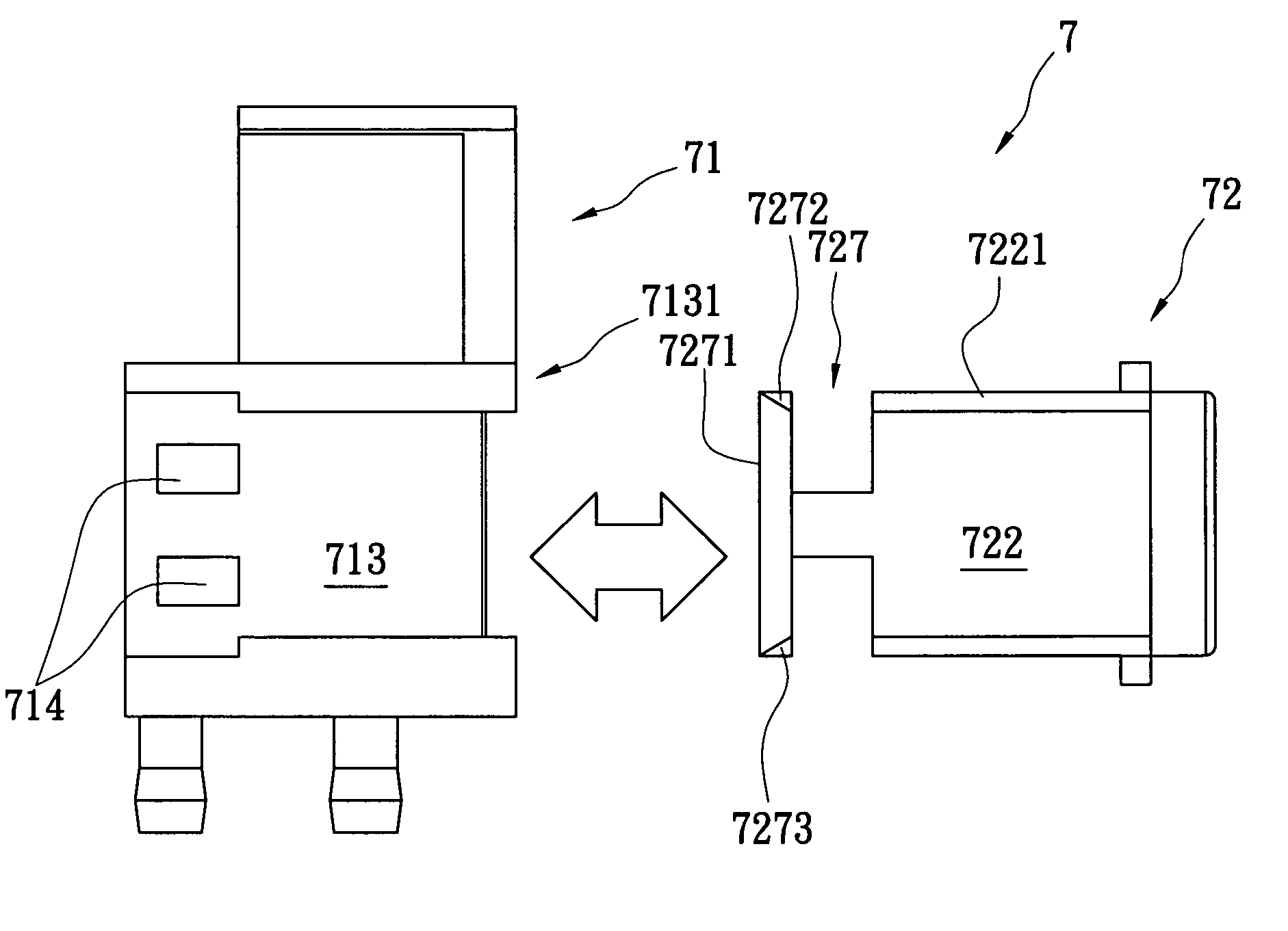
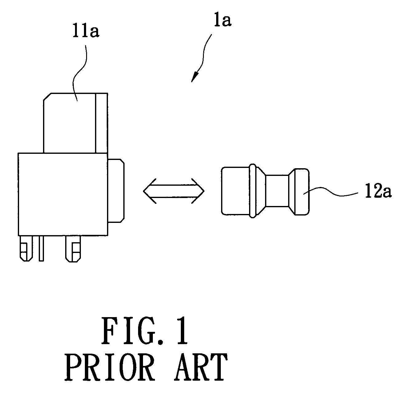
[0045]The present invention provides an optical fiber connector that mates with an optical fiber coupling, and the optical fiber connector utilizes a U-shaped portion assembled to a housing thereof. The housing has two clamping grooves respectively arranged on upper and lower edges of each opposite lateral outer surface thereof, in order to engage with two side plates to connect to a socket frame of the U-shaped portion. The U-shaped portion includes a shutter downwardly extending from an upper front edge thereof. The housing and the U-shaped portion combine as the optical fiber connector with a dust-proof plate. The structure of the present invention is accordingly simple and durably, easy to assemble and to test, so as to increase assembly and testing efficiencies and reduce the costs. The present invention further avoids a choking hazard for children, which might happen in the first conventional optical fiber connector 1a that is made with two pieces.

[0046]Referring to FIGS. 6A t...


PUM


Abstract

An optical fiber connector for mating with an optical fiber coupling has a housing and a U-shaped portion assembled to the housing. The housing has two clamping grooves respectively formed on upper and lower edges of each opposite lateral outer surface thereof. The U-shaped portion includes a socket frame and two side plates extending from the socket frame. The socket frame includes a shutter downwardly extending from an upper front edge thereof and made integrally in one piece. Each of the side plates has two engaging faces respectively retained in the clamping grooves and arranged on upper and lower edges thereof.

Description

[0001]This Nonprovisional application claims priority under 35 U.S.C. § 119(a) on Patent Application No(s). 092128425 filed in Taiwan on Oct. 14, 2003, the entire contents of which are hereby incorporated by reference.BACKGROUND OF THE INVENTION[0002]1. Field of the Invention[0003]The present invention relates to an optical fiber connector, and particularly relates to an optical fiber connector for light coupling.[0004]2. Background of the Invention[0005]With optical fiber communication developing, requirements for optical fiber connectors are increased. Each optical fiber connector always works with an optoelectronic component, and an entrance of the optical fiber connector must be completely enclosed to prevent dust and other external objects from affecting optical signals and to protect users' eyes from light emitted by the optical fiber connector.[0006]With respect to FIG. 1, a dust-proof bung 12a is removable from a first conventional optical fiber connector 1a to mate with an ...

Claims


Application Information

Patent Timeline
Patent Type & Authority Patents(United States)
IPC IPC(8): G02B6/36G02B6/42
CPCG02B6/4292G02B2006/4297
Inventor WANG, KUN-SHENG
Owner LITE ON TECH CORP
Why Eureka
Try Eureka