Orthodontic separators

a separator and orthodontic technology, applied in the field of teeth separation, can solve the problems of separator products that start out separating teeth quickly and lose their effect, separators become lost in the mouth, and separators are easily inserted or removed, and achieve the effect of satisfying the resistance to force degradation and being easy to insert or remov

Inactive Publication Date: 2006-01-24
3M INNOVATIVE PROPERTIES CO
View PDF34 Cites 24 Cited by
  • Summary
  • Abstract
  • Description
  • Claims
  • Application Information

AI Technical Summary

Benefits of technology

[0009]The orthodontic separator can be designed to expand isotropically or anisotropically. It can also continue to expand over time, exerting a compressive force on the adjacent teeth despite the widening gap between the teeth and decay in compressive force resulting from relaxation of the separator. In addition, it can provide satisfactory resistance to force degradation over extended periods of time (e.g., the amount of time the separator is used in t

Problems solved by technology

Inserting separators is often difficult, especially when the space between the adjacent teeth is small.
Currently, separator products start out separati

Method used


Image

  • Orthodontic separators
  • Orthodontic separators
  • Orthodontic separators

Examples


example 1

[0039]Compressive force measurements were recorded for tubing samples made of TECOPHILIC HP-93A-100-B20 using the compressive force measurement test procedure with the exception that the gap distance was set slightly less than the tubing length to hold the tubing in place after insertion. The samples tested had an inner diameter of 0.050″, an outer diameter of 0.074″ and a length of 0.138.″ The initial compressive forces for the two samples were 40 g and 100 g for samples 1 and 2, respectively. FIG. 5 plots the increase in compressive force over time for the two samples. Within 10 minutes, the force increase for samples 1 and 2 was about 100 g. By 20 minutes, the force increase for sample 2 was about 200 g.

example 2

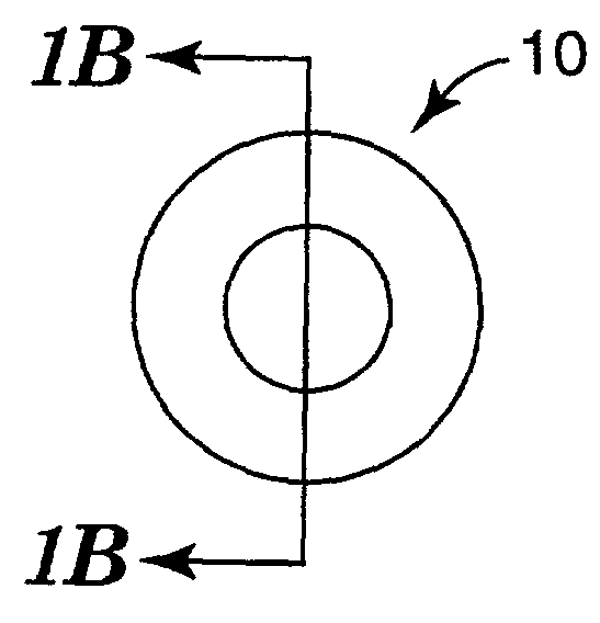
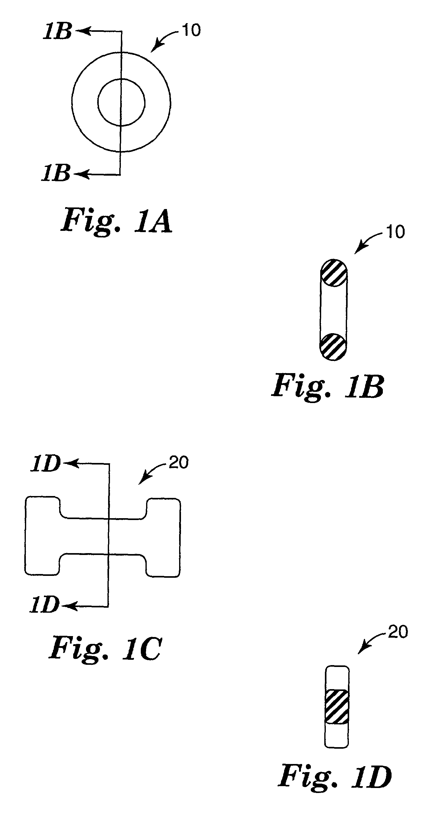
[0040]Two sets of separators were injection molded into an O-ring shape with an inner diameter of 0.085 inches, an outer diameter of 0.175 inches, and a thickness of 0.045 inches. One set contained no barium sulfate, and one set contained 20 wt % barium sulfate. Two radio-opaque control samples (Control A and Control B) were commercially available SX separators (3M Unitek 406-086, Monrovia, Calif.) with an inner diameter of 0.090 inches, an outer diameter of 0.190 inches, and a thickness of 0.050 inches The control samples contained 20 wt % barium sulfate.

[0041]Compressive force measurements were recorded for the three sets of separators using the compressive force measurement test procedure. FIG. 6 plots compressive force over time for each of the three sets of separators. The results from these measurements at time zero and after 1.5 hours are given in Table 1. Upon absorbing water, the separators made from the HP-93A-100 TECOPHILIC material (both with and without barium sulfate) ...

example 3

[0043]This example describes the extent and rate of expansion for separators prepared from TECOPHILIC HP-93A-100 with and without barium sulfate. The separators were injection molded according to the procedure described in Example 2. Expansion was characterized by percent weight gain upon water absorption. Percent weight gain was calculated as (W−W0) / W0×100, where W0 was the initial separator weight (dry), and W was the separator weight at time t (wet). Initial separator weights were taken at atmospheric conditions. Separators were then immersed in 37° C. water. The separators were removed at different time points, blotted dry to remove excess water, and weighed. FIG. 7 shows the percent weight gain over time for the two separators. Water absorption occurred rapidly in the first 2 hours and slowly afterwards. Weight gain reached 75% and 64% for the separators without and with barium sulfate, respectively, after immersion in 37° C. water for 16 hours.


PUM


Abstract

An orthodontic separator, dimensioned such that it can be inserted between adjacent teeth. The separator is characterized in that it exhibits an increase in compressive force after insertion between adjacent teeth in the oral environment. The separator, after insertion, exerts sufficient force on the adjacent teeth to push the teeth apart.

Description

BACKGROUND OF THE INVENTION[0001]1. Field of the Invention[0002]This invention relates to separating teeth.[0003]2. Description of the Related Art[0004]Orthodontic treatment generally involves application of mechanical forces to urge improperly positioned teeth into correct alignment. One common form of orthodontic treatment includes the use of elastomeric separators to increase the space between teeth before fitting orthodontic bands. The materials used for elastomeric separators are typically hydrophobic polyurethanes. During insertion of an elastomeric separator, the separator is stretched and inserted between adjacent teeth using a sawing action. Tools that may be used to stretch and insert separators include dental floss and pliers.[0005]Inserting separators is often difficult, especially when the space between the adjacent teeth is small. Once inserted between adjacent teeth, the separator is under compression and generates a force to separate the adjacent teeth. Currently, se...

Claims


Application Information

Patent Timeline
IPC IPC(8): A61C7/00A61C7/10A61C7/22
CPCA61C7/00A61C7/10A61C2201/007A61C2201/005A61C7/22
Inventor HANSEN, JAMES D.TZOU, TSI-ZONG
Owner 3M INNOVATIVE PROPERTIES CO
Why Eureka
Try Eureka