Cryo balloon

a balloon and cryoablation technology, applied in the field of cryo therapy, can solve the problems of untoward healing response, destroying the function of abnormal tissue in an area of interest, and causing atrial fibrillation

Inactive Publication Date: 2006-01-24
BOSTON SCI SCIMED INC
View PDF54 Cites 307 Cited by
  • Summary
  • Abstract
  • Description
  • Claims
  • Application Information

AI Technical Summary

Problems solved by technology

Ablative techniques, generally, result in destroying the function of abnormal tissue at an area of interest.
Moreover, atrial fibrillation may be caused by abnormal activity within a isolated focal center within the heart.
The use of RF energy for ablation may, however, lead to untoward healing responses such as collagen build up at the area of interest after treatment.
Moreover, RF ablation of within an atrium may decrease atrial output.

Method used


Image

  • Cryo balloon
  • Cryo balloon
  • Cryo balloon

Examples


Embodiment Construction

[0014]The following description should be read with reference to the drawings wherein like reference numerals indicate like elements throughout the several views. The detailed description and drawings represent select embodiments and are not intended to be limiting.

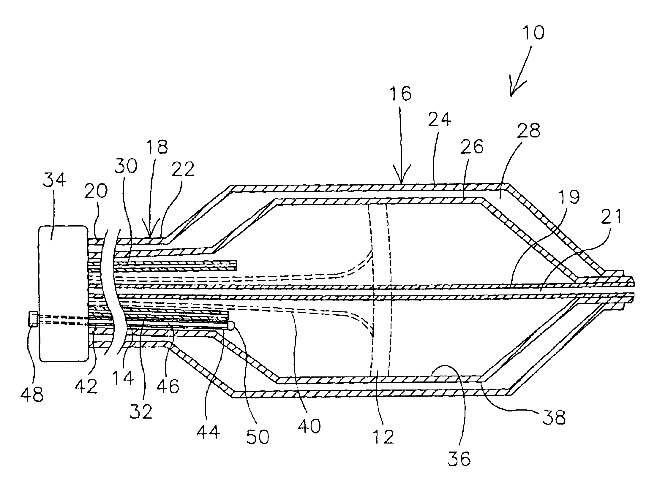
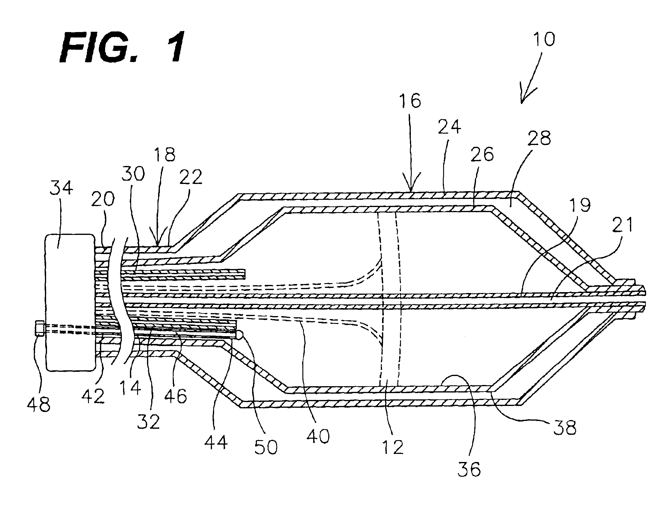
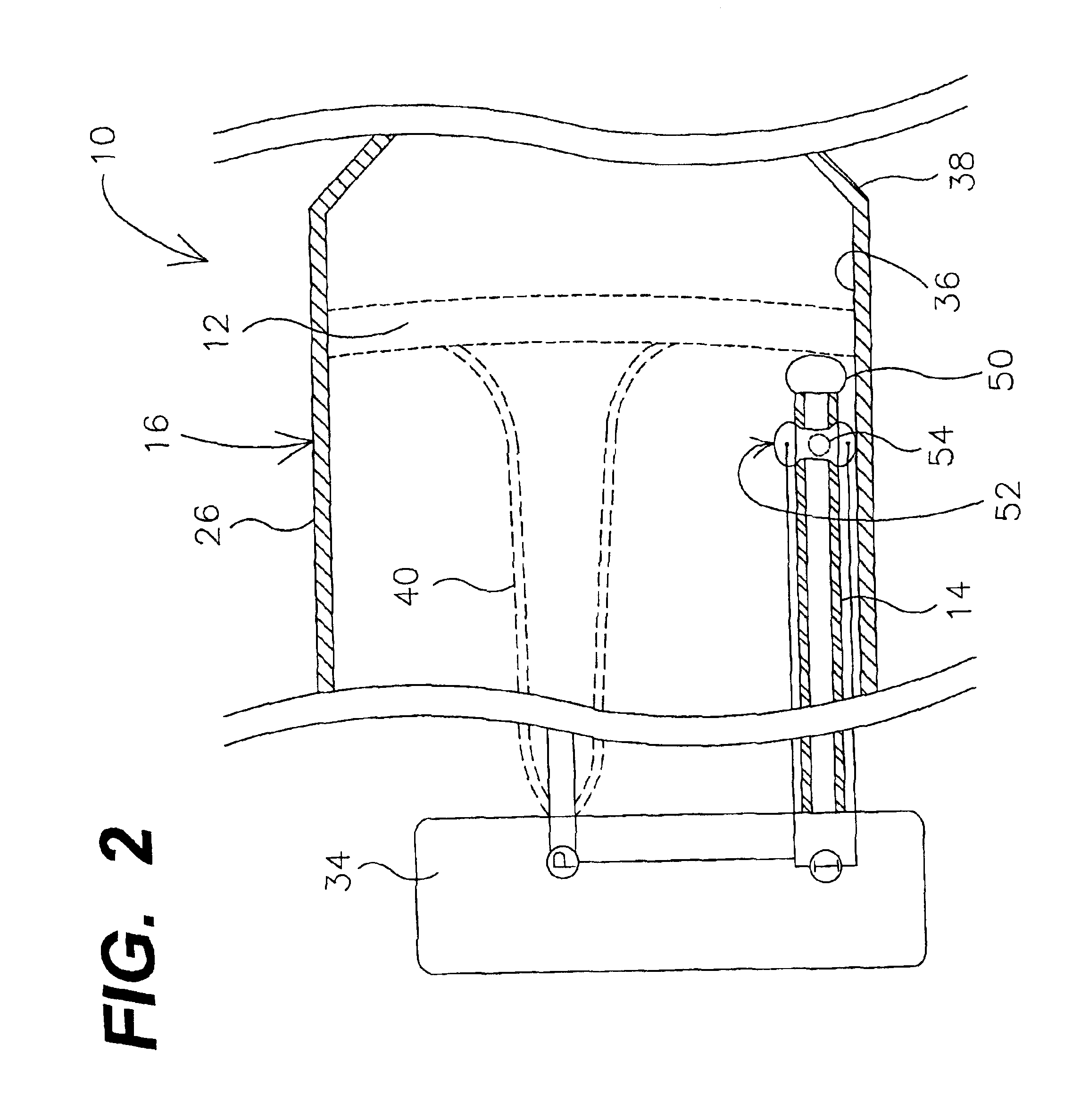
[0015]FIG. 1 is a cross-section of a cryo therapy device 10 having a pressure gauge 12 and a pressure release tube 14. Pressure gauge 12 is coupled to a cooling member 16, for example on an inner member 26. Pressure gauge 12 may be used to quantify pressure within cooling member 16. Cooling member 16 is coupled to an elongate shaft 18. In addition, at least a portion of pressure relief tube 14 is disposed within cooling member 16. Pressure relief tube 14 may be used to release inflation / cooling media from cooling member 16. This could be done, for example, when the pressure in cooling member 16 as detected by gauge 12 is in excess of a desired limit.

[0016]Cryo therapy device 10 may use heat transfer to perform a number of...


PUM


Abstract

Devices and methods for performing cryo therapy, cryo ablation or cryoplasty. A cryo therapy apparatus may comprise an elongate shaft, a cooling member disposed at the distal end of the shaft, and a pressure gauge coupled to the cooling member.

Description

FIELD OF THE INVENTION[0001]The present invention pertains generally to the field of cryo therapy. More particularly, the present invention pertains to cryo ablation catheters for use in causing cold-induced necrosis and cryoplasty catheters for use in causing apoptosis to prevent restenosis.DESCRIPTION OF THE RELATED ART[0002]A number of medical conditions may be treated using ablative techniques or devices. Ablative techniques, generally, result in destroying the function of abnormal tissue at an area of interest. Destroying the function of the abnormal tissue may result in an efficacious treatment for a medical condition. For example, atrial fibrillation may be the result of abnormal electrical activity in the left atrium and the pulmonary vein, and may be treatable by ablation of the abnormal tissue within the left atrium and / or the pulmonary vein.[0003]Atrial fibrillation is a serious medical condition that is the result of abnormal electrical activity within the heart. This ab...

Claims


Application Information

Patent Timeline
Patent Type & Authority Patents(United States)
IPC IPC(8): A61M29/02A61B17/22A61B18/02A61B19/00
CPCA61B18/02A61B2017/22051A61B2019/464A61B2018/0212A61B2018/0262A61B2018/0022A61B2090/064
Inventor LAFONTAINE, DANIEL M.
Owner BOSTON SCI SCIMED INC
Why Eureka
Try Eureka