Variable power optical system

a variable power, optical system technology, applied in optics, instruments, lenses, etc., can solve the problems of limited power ratio, unsuitable front projection use, difficult to maintain the compactness of the optical system, etc., and achieve the effect of suppressing the occurrence of various aberrations

Active Publication Date: 2006-01-24
CANON KK
View PDF22 Cites 23 Cited by
  • Summary
  • Abstract
  • Description
  • Claims
  • Application Information

AI Technical Summary

Benefits of technology

The present invention proposes a compact variable power optical system that can achieve a desired power ratio without causing various aberrations such as chromatic aberration of magnification. The system has a first optical component with a curved surface and a second optical component with movable lens units that change the focal length. The second optical component forms an image of a reduction side conjugate point on the enlargement side. The technical effect of this invention is to provide a reliable and efficient variable power optical system that can be used in various optical devices such as cameras, microscopes, and projectors.

Problems solved by technology

The patent text discusses various methods and designs for realizing a wide angle of view and a compact optical system for projecting an image. However, each method has its limitations and drawbacks, such as the inability to correct trapezoidal distortion and the enlargement of various aberrations. The patent text proposes a solution to overcome these limitations by using a diffraction optical element and a rotationally asymmetrical reflecting surface with a curved aper to achieve a wide angle of view and a compact optical system. The technical problem addressed in the patent text is to create an off-axis optical system that can correct trapezoidal distortion and achieve a wide angle of view without enlarging the aberrations caused by the reflecting optical system. The patent text also discusses various techniques for realizing a wide angle of view and downsizing the optical system.

Method used


Image

  • Variable power optical system
  • Variable power optical system
  • Variable power optical system

Examples


Embodiment Construction

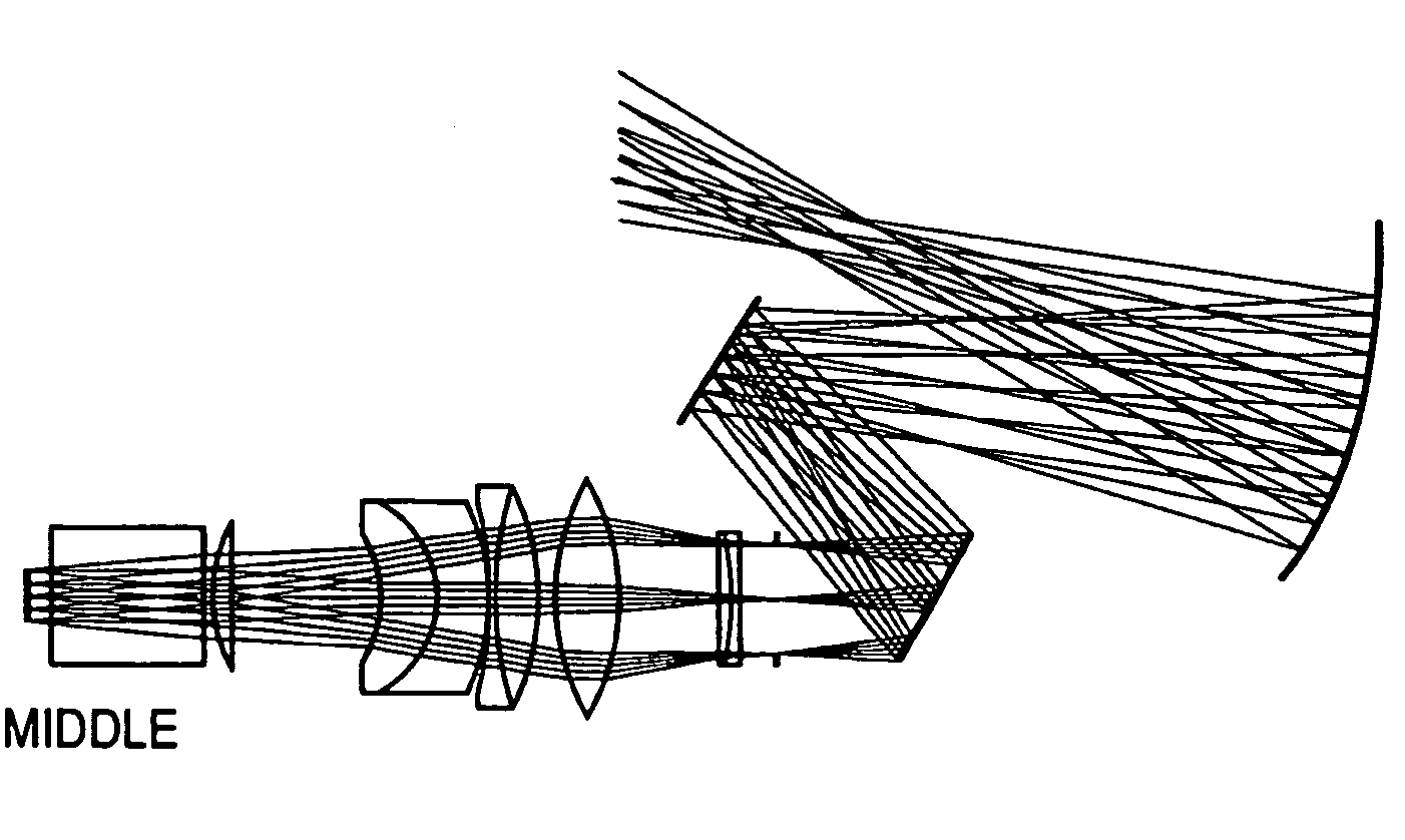
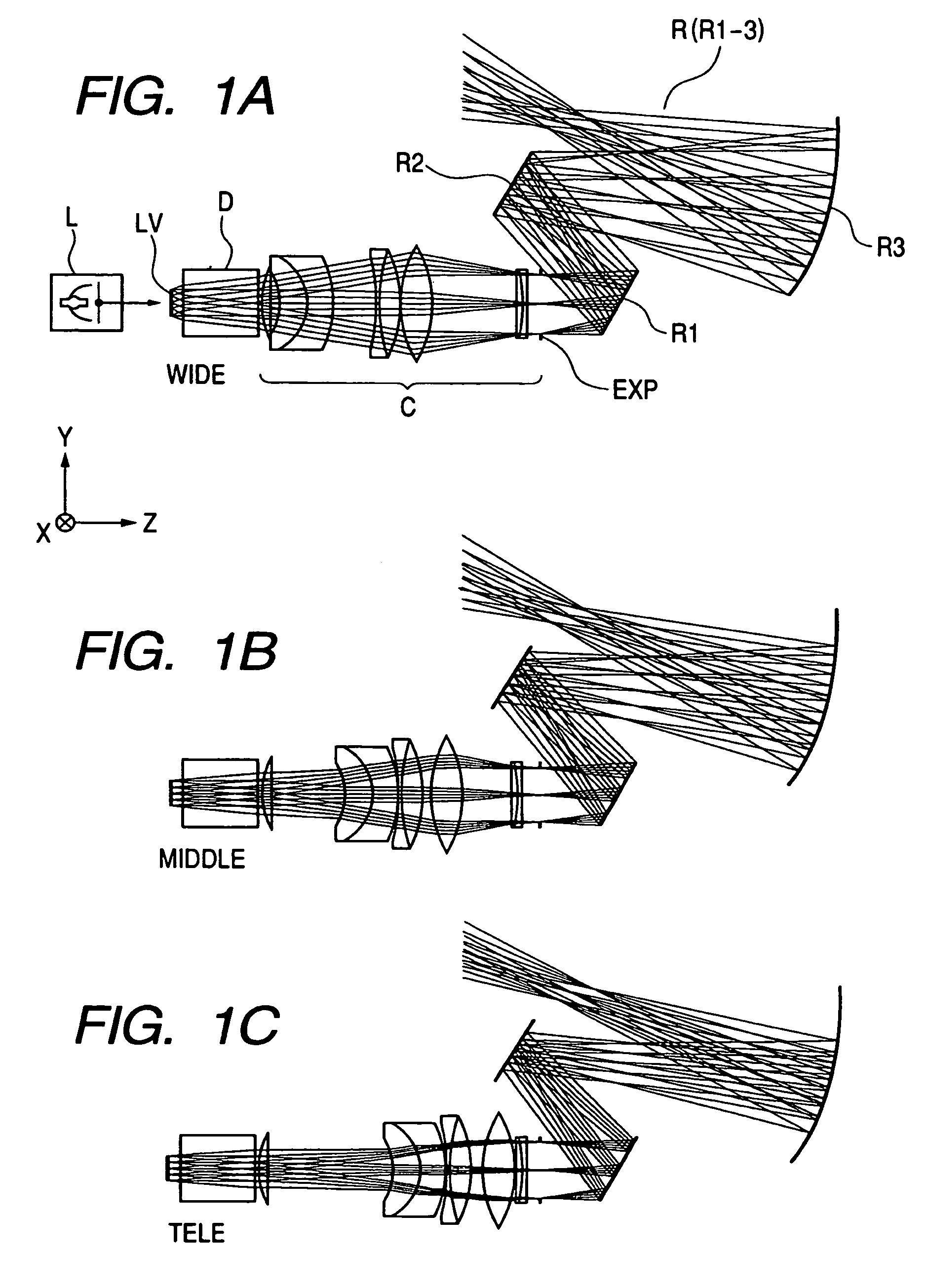
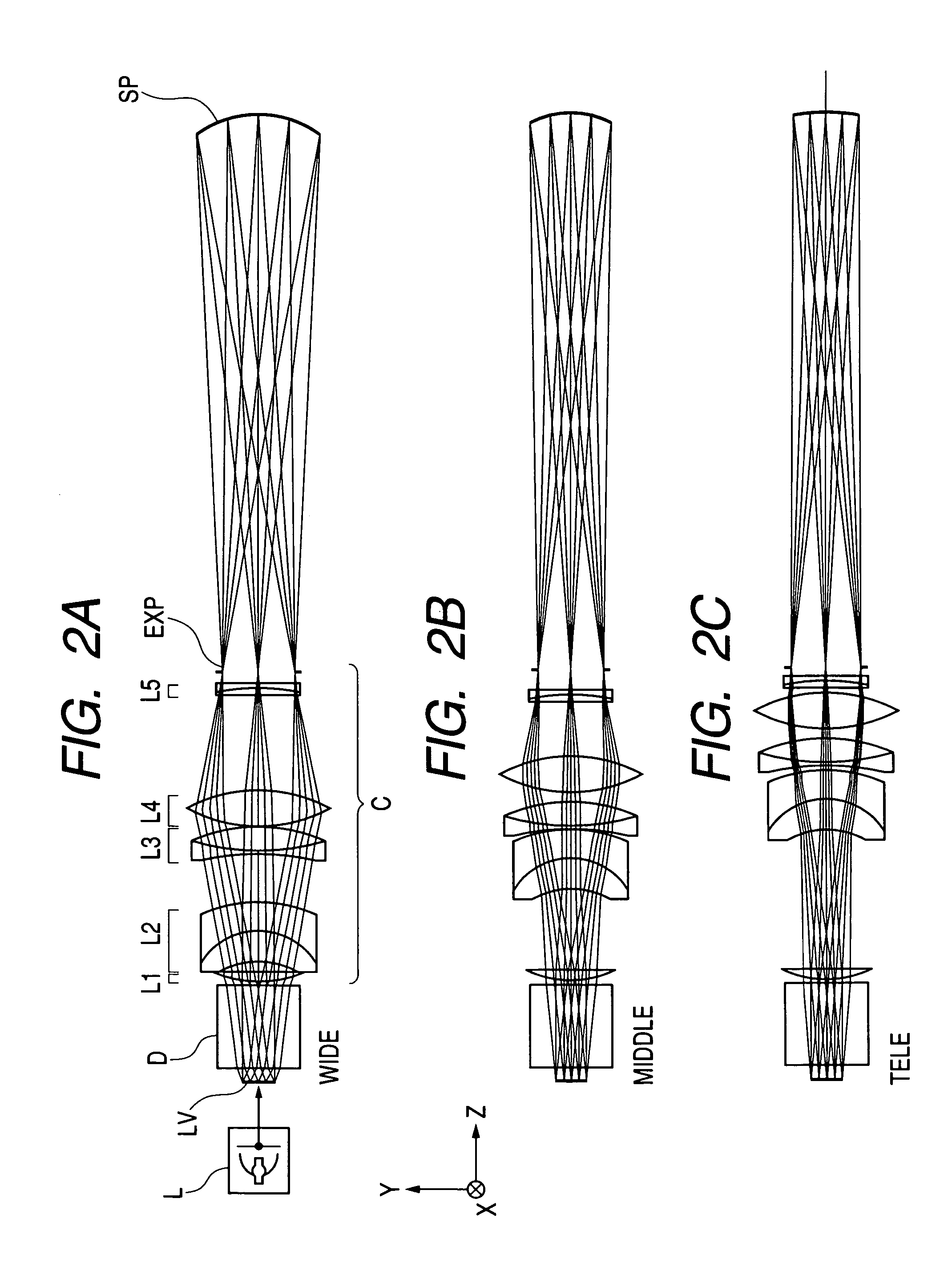
[0029]Before explaining the embodiment of the present invention, explanation will be first made to the way of representing the constituent elements of the embodiment and the common items of the entire embodiment. FIG. 9 is an illustration of a coordinate system defining the construction data of an optical system. In the present embodiment, the ith surface along a ray (indicated by a dot-and-dash line in FIG. 9 and called the reference axis ray) travelling from the reduction side to the image plane on the enlargement side is defined as the ith surface. Also, in the present description, a plane onto which an image is projected is expressed as a screen or a predetermined image plane, and the projected image is expressed as an image, an image plane or an image field, and can be freely substituted for. Also, in the embodiment, description will be made in a form wherein the image is projected onto the predetermined image plane on the enlargement side with the reduction side as the object ...


PUM


Abstract

The optical system disclosed in this specification is a variable power optical system for enlarging and projecting a reduction side object onto an enlargement side image plane, or reducing and projecting an enlargement side object onto a reduction side image plane. This variable power optical system includes a first optical component having a reflecting curved surface, and a second optical component disposed more toward the reduction side than the first optical component. The second optical component has a plurality of movable lens units, and the variable power optical system effects a variable power operation by movement of the plurality of lens units. If ray was traced from the reduction side toward the enlargement side, the second optical component forms an image of a reduction side conjugate point on the enlargement side than an optical surface of the first optical component that is most adjacent to the reduction side.

Description


Claims


Application Information

Patent Timeline
Owner CANON KK
Why Eureka
Try Eureka