X-ray optical system for small angle scattering

a small angle scattering and optical system technology, applied in the direction of material analysis using wave/particle radiation, instruments, diaphragm/collimeter handling, etc., can solve the problem of not being able to be easily switched to other x-ray incident optical systems for x-ray analysis, and achieve the effect of convenient switching

Active Publication Date: 2006-01-24
RIGAKU CORP
View PDF9 Cites 13 Cited by
  • Summary
  • Abstract
  • Description
  • Claims
  • Application Information

AI Technical Summary

Benefits of technology

[0012]In the present invention, the first slit of the X-ray optical system for small angle scattering of the conventional three-slit system is omitted, and the multilayer mirror is used in place thereof. Consequently, the X-ray optical system for small angle scattering can be easily switched to other X-ray incident optical systems for X-ray analysis. Furthermore, since the multilayer mirror is used, a monochromatic X-ray beam having X-ray intensity larger than that of the conventional X-ray optical system for small angle scattering can be obtained.

Problems solved by technology

Since the three-slit optical system is a special optical system, this cannot be easily switched to other X-ray incident optical systems for X-ray analysis.

Method used


Image

  • X-ray optical system for small angle scattering
  • X-ray optical system for small angle scattering
  • X-ray optical system for small angle scattering

Examples


Embodiment Construction

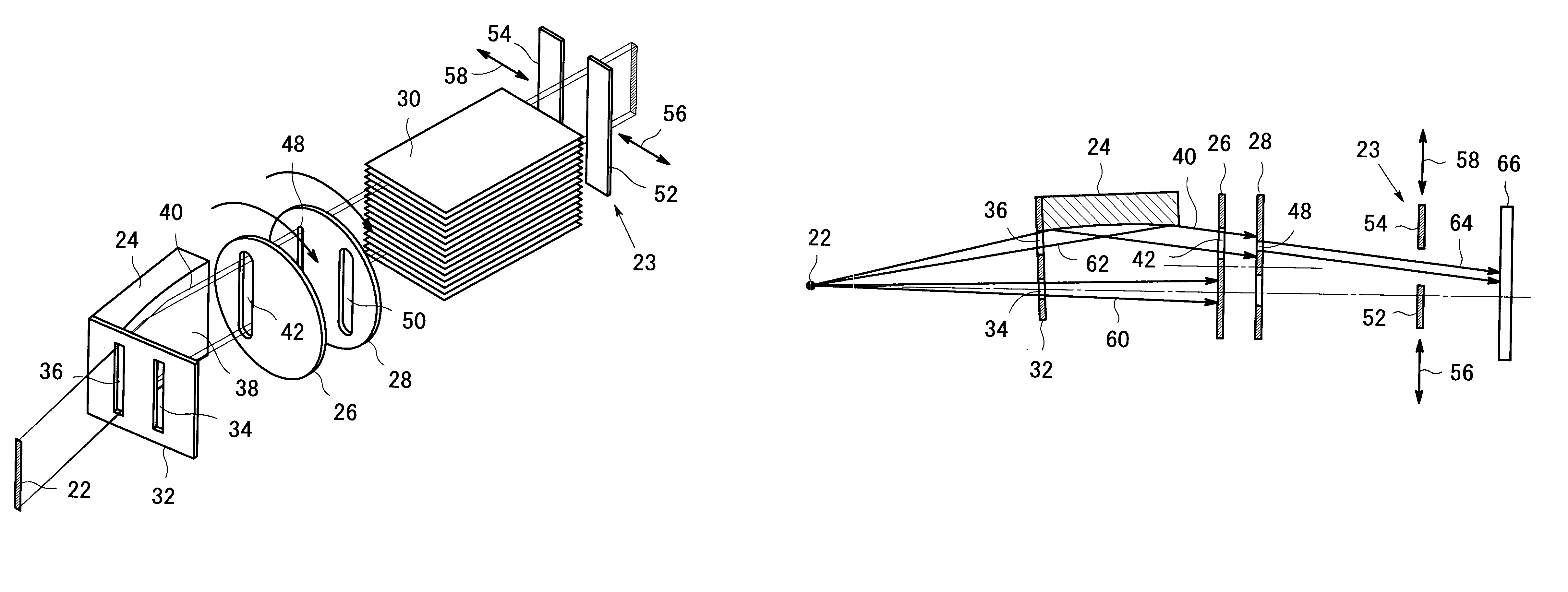
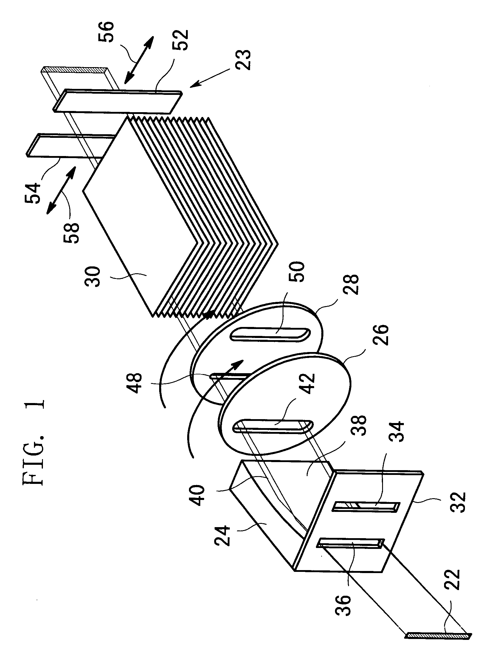
[0021]Referring to FIG. 1 illustrating the first embodiment of the present invention, a multilayer mirror 24, an optical-path selecting slit device 26, a small-angle selecting slit device 28 and a Soller slit 30 are arranged between an X-ray source 22 and a specimen-side slit 23 in the described order from the X-ray source side. These constituents will be described below in detail.

[0022]An aperture slit plate 32 is fixed, with screws, on the end surface of the multilayer mirror 24 and has a first aperture 34 and a second aperture 36. An X-ray beam having passed through the first aperture 34 bypasses the multilayer mirror 24 and travels toward a specimen, this condition being to be described in detail below with reference to FIG. 5. The X-ray beam having passed through the second aperture 36 is reflected at a reflecting surface 38 of the multilayer mirror 24 to become a parallel beam 40 and travels toward the specimen. Both of the two apertures 34 and 36 have dimensions of 0.9 mm in ...


PUM

PropertyMeasurementUnit
angle of divergenceaaaaaaaaaa
widthaaaaaaaaaa
distanceaaaaaaaaaa

Abstract

An X-ray optical system for small angle scattering has a parabolic multilayer mirror and, so that switching to other X-ray incident optical systems for X-ray analysis can be easily performed. A parabolic multilayer mirror, an optical-path selecting slit device, a small-angle selecting slit device and a Soller slit are arranged between an X-ray source and a specimen-side slit. An X-ray beam having passed through the first aperture of an aperture slit plate is interrupted by the optical-path selecting slit. An X-ray beam having passed through the second aperture of the aperture slit plate is reflected at the reflecting surface of the multilayer mirror to become a parallel beam. This parallel beam passes through an aperture of the optical-path selecting slit device. The beam width is restricted by a narrow slit of the small-angle selecting slit device.

Description

BACKGROUND OF THE INVENTION[0001]1. Field of the Invention[0002]The present invention relates to an X-ray optical system for small angle scattering to prepare an X-ray beam incident on a specimen in an X-ray small angle scattering apparatus.[0003]2. Description of the Related Art[0004]When an X-ray beam is incident on a specimen, the X-ray scatters with an angle in a range within a small angle (a small angle region) in the vicinity of the travelling direction of the X-ray beam, this being referred to as small angle scattering. Measurement of the small angle scattering provides various pieces of information, including a grain size, a periodic structure and the like, on the specimen material. An apparatus for measuring the above-described small angle scattering is referred to as an X-ray small angle scattering apparatus, and an optical system specific thereto (an optical system for preparing an X-ray beam to be incident on a specimen) is referred to as an X-ray optical system for smal...

Claims


Application Information

Patent Timeline
Patent Type & Authority Patents(United States)
IPC IPC(8): G21K1/02G01N23/201
CPCG01N23/201
Inventor FUJINAWA, GOOKANDA, HITOSHI
Owner RIGAKU CORP
Why Eureka
Try Eureka