
Stencil printing machine

Inactive Publication Date: 2006-01-31
RISO KAGAKU CORP
View PDF14 Cites 6 Cited by
  • Summary
  • Abstract
  • Description
  • Claims
  • Application Information

AI Technical Summary

Benefits of technology

[0026]Furthermore, the control means may control the timing with which the printing drum is rotated to start loading of the stencil sheet such that the timing is a same timing as the timing with which the writing head completes forming a perforated image on the stencil sheet.
[0027]In particular, by controlling the timing such that the writing head starts stencil loading at the same timing as completion of formation of a perforated image on the stencil sheet, the first print time can be shortened by the stencil making pressure release time period T. Moreover, the control operation can be simplified.

Problems solved by technology

As described above, in the conventional stencil printing machine, there has been a disadvantage that the first print time is long because of serial processing of the stencil making, stencil making pressure release, stencil loading, cutting, and printing / printed sheet discharged operations.

Method used


Image

  • Stencil printing machine
  • Stencil printing machine
  • Stencil printing machine

Examples


Embodiment Construction

[0034]Hereinafter, a description will be given of an embodiment of the present invention with reference to the drawings.

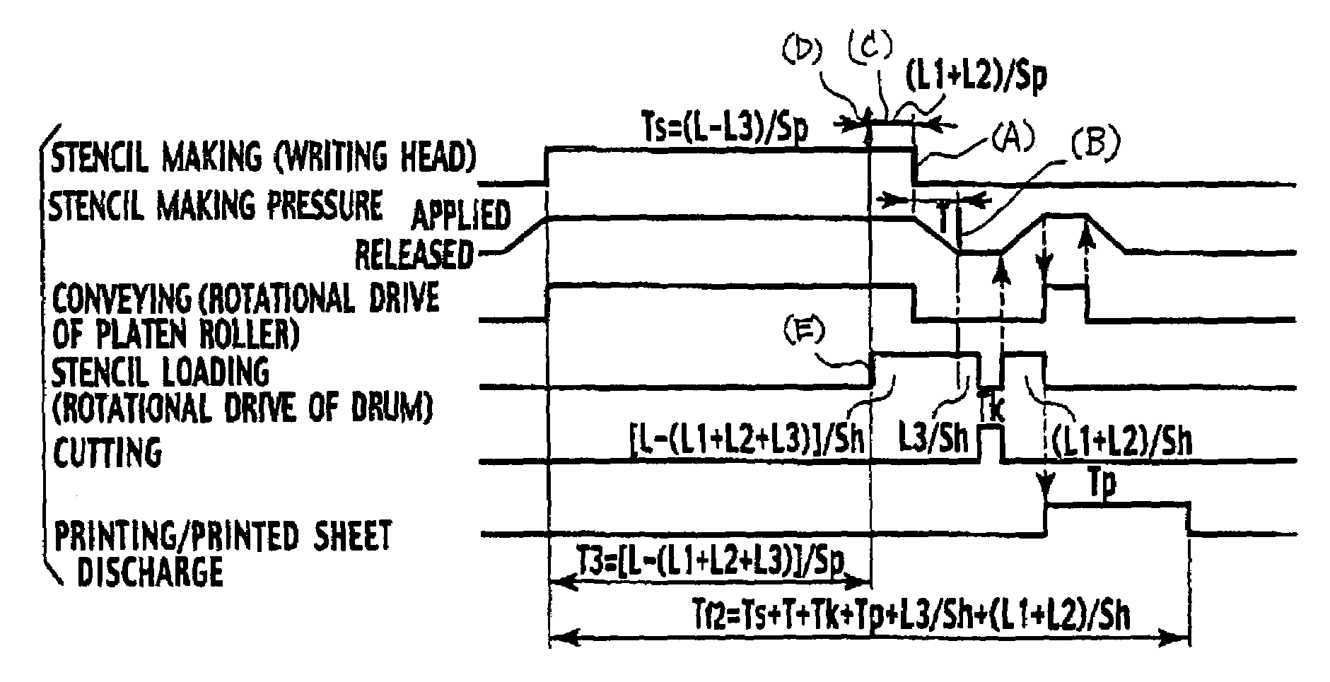
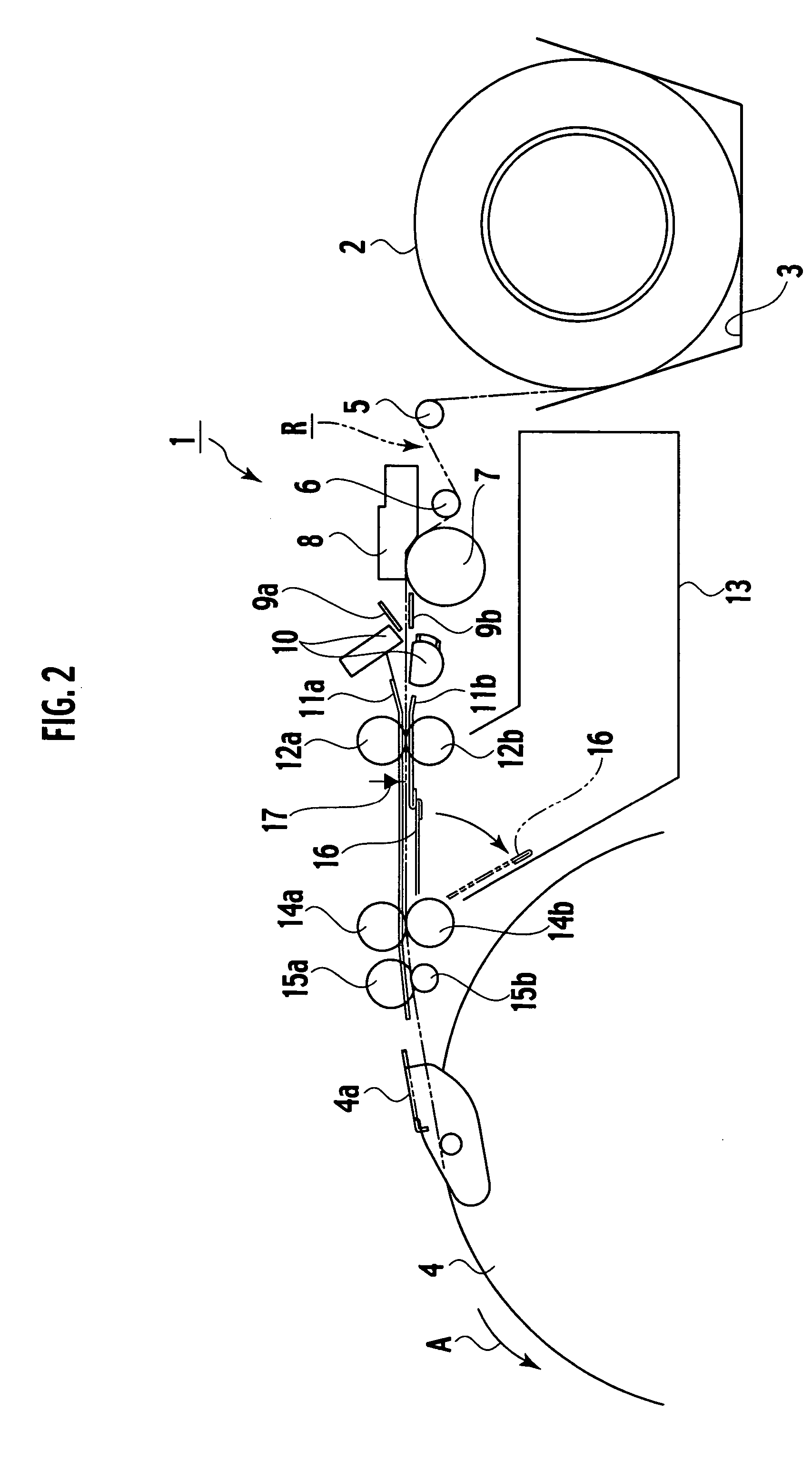
[0035]FIG. 2 to FIG. 6C show an embodiment of the present invention. FIG. 2 is a schematic drawing of a stencil making unit of a stencil printing machine according to the present invention, FIG. 3 is a block diagram of main parts related to the stencil making unit and the like of the stencil printing machine, FIGS. 4A to 4C and FIGS. 5A to 5C are schematic views explaining a stencil loading operation, and FIGS. 6A to 6C are time charts related to a first print time.

[0036]As shown in FIG. 2, a stencil making unit 1 includes a stencil sheet roll container 3 which accommodates a roll stencil sheet 2. A conveying route R (indicated by a chain double-dashed line in FIG. 2) is formed between the stencil sheet roll container 3 and a stencil sheet clamp section 4a of a printing drum 4.

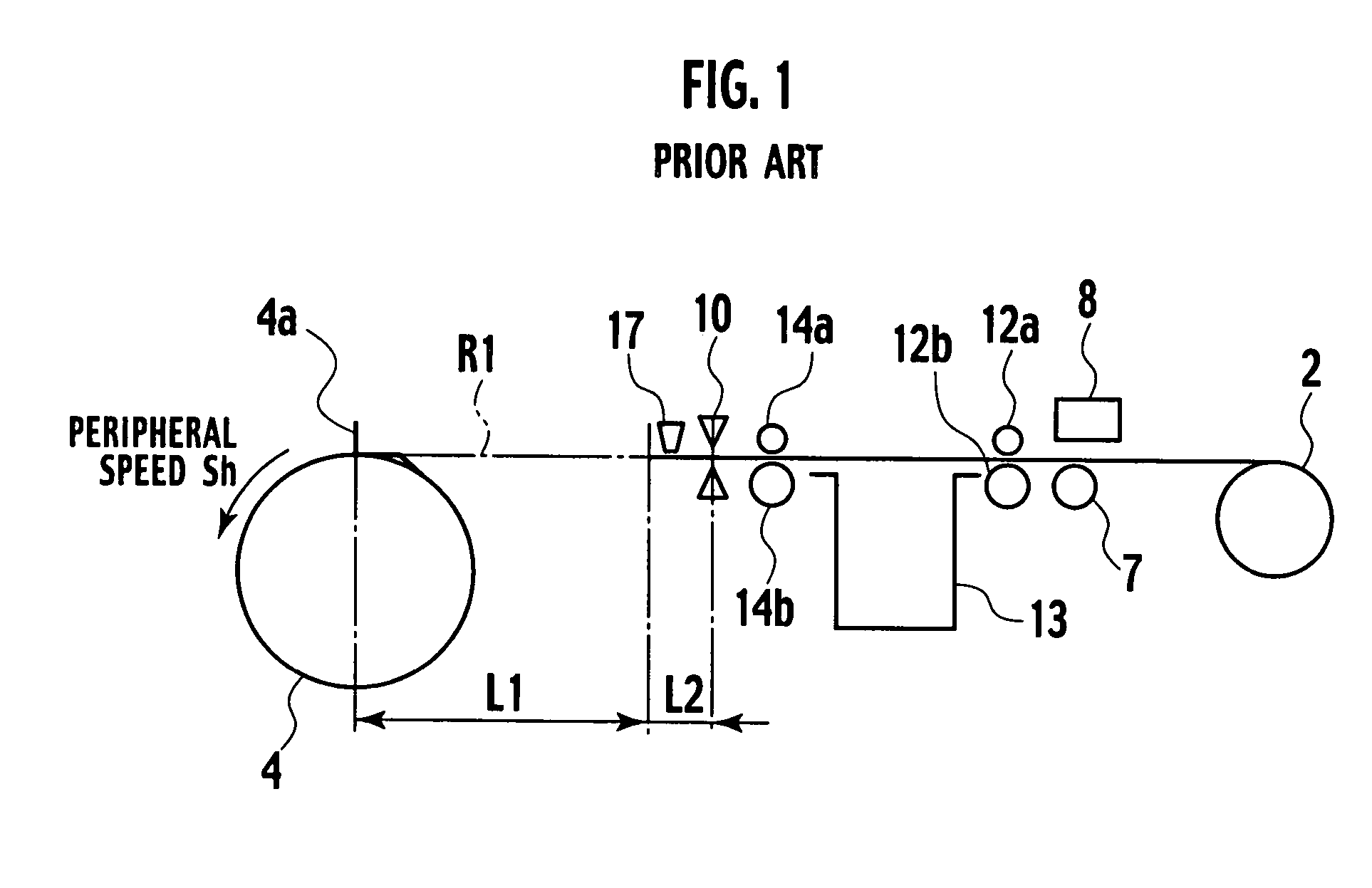
[0037]The conveying route R includes: a first guide roller 5 placed just downstream of th...


PUM


Abstract

A conveying route along which the leading edge side of a roll stencil sheet is conveyed to a stencil sheet clamp section of a printing drum is formed. Along the conveying route, arranged are: a writing head which forms a perforated image on the stencil sheet; a platen roller on which the writing head is brought into pressure contact and which conveys the stencil sheet; a stencil sheet cutter which cuts the stencil sheet; a stencil positioning sensor which detects a leading edge of the stencil sheet; and storage means for temporarily storing the stencil sheet. Control means for controlling a timing with which the printing drum is rotated to start loading of the stencil sheet is included, the control means controlling the timing to be an arbitrary time between an earliest timing earlier, by a time period obtained by dividing a conveying distance between the stencil sheet cutter and the stencil sheet clamp section by a peripheral speed of the platen roller, than a timing with which the writing head completes forming a perforated image on the stencil sheet and a latest timing which is a same timing as completion of release of stencil making pressure.

Description

BACKGROUND OF THE INVENTION[0001]1. Field of the Invention[0002]The present invention relates to a stencil printing machine which creates a printed sheet by forming a perforated image on a stencil sheet based on image data and transferring ink to a print medium through this perforated image on the stencil sheet. Specifically, the present invention relates to a technology for shortening a first print time to form the perforated image and output a first trial print.[0003]2. Description of the Related Art[0004]A conventional stencil printing machine is described in Japanese Patent Laid-Open publication No. Hei 9(1997)-11600. FIG. 1 is a schematic drawing showing main parts of the stencil printing machine described in the publication, the parts being related to stencil making and loading. In FIG. 1, a rolled stencil sheet 2, a writing head 8, a platen roller 7, a pair of first conveyer rollers 12a and 12b, a storage box 13, a pair of second conveyer rollers 14a and 14b, a stencil sheet ...

Claims


Application Information

Patent Timeline
IPC IPC(8): B41L13/14B41L13/04B41L13/06
CPCB41L13/06
Inventor KATO, KAZUHIRO
Owner RISO KAGAKU CORP
Learn More