
Installation device and installation method for piston ring

Inactive Publication Date: 2007-03-15
HIRATA & CO LTD
View PDF9 Cites 1 Cited by
  • Summary
  • Abstract
  • Description
  • Claims
  • Application Information

AI Technical Summary

Benefits of technology

[0010] According to this structure, when the extruding mechanism extrudes a lowest piston ring and returns to the waiting position, the extruding mechanism is pre-driven downwardly in the vertical direction. Therefore, the extruding mechanism can avoid coming into contact with a piston ring waiting for the next processing at the lowest part of the magazine, and hence the piston ring held by the magazine can be prevented from, for example, being deviated. Additionally, since the extruding mechanism is driven in the horizontal direction and in the vertical direction, the structure can be made simpler than driven in the oblique direction, and a fine adjustment can be easily performed for the height position of the extruding mechanism with respect to a piston ring, thus making it possible to perform highly accurate positioning. Still additionally, since the ring holding mechanism is reciprocated only in one direction, the structure can be simplified, and the device can be reduced in size. Still additionally, since the ring diameter extending mechanism can freely enter and leave the guide passage formed by the ring holding mechanism, the guide passage of the piston ring is always maintained (secured) further reliably than is disposed in a free space lying between the guide passage and the piston (a free space lying between the guide passage formed by being interrupted midway and the piston) as in the conventional technique. Hence, the piston ring can be reliably fitted into the ring groove without being deviated from the normal position.
[0024] According to this structure, in the extruding step, the push-out member is pre-driven downwardly in the vertical direction when the push-out member returns to the waiting position after extruding a lowest piston ring. Therefore, the push-out member can avoid coming into contact with a piston ring waiting for the next processing at the lowest part of the magazine, and hence the piston ring held by the magazine can be prevented from, for example, being deviated. Additionally, since the extruding step is performed to drive the push-out member in the horizontal direction and in the vertical direction, compared to the case that the push-out member is driven in the oblique direction, a fine adjustment can be easily performed for the height position of the push-out member with respect to a piston ring, thereby making it possible to perform highly accurate positioning. Still additionally, in the ring diameter extending step, since the piston ring is extended by driving the diameter extending member only in one direction, the sequence that controls the operations can be simplified. Still additionally, in the ring inserting step, since a state in which the surrounded guide passage is always maintained is reached, even when the diameter extending member recedes from the guide passage, the piston ring is reliably fitted into the ring groove without being deviated.

Problems solved by technology

Therefore, there is a risk that functional reliability will be lowered.
Therefore, there is a risk that positioning cannot be performed with high accuracy.
Additionally, in the conventional installation device, the ring guide member and the ring diameter extending member are radially reciprocated, and hence the structure becomes complex, and the device is increased in size.
Therefore, there is a risk that the ring R will be disengaged from the ring groove Gas shown in FIG. 1C, and cannot be reliably fitted therein to when the ring R is shaped like a wave.

Method used


Image

  • Installation device and installation method for piston ring
  • Installation device and installation method for piston ring
  • Installation device and installation method for piston ring

Examples


Embodiment Construction

[0044] Preferred embodiments of the present invention will be hereinafter described with reference to the drawings.

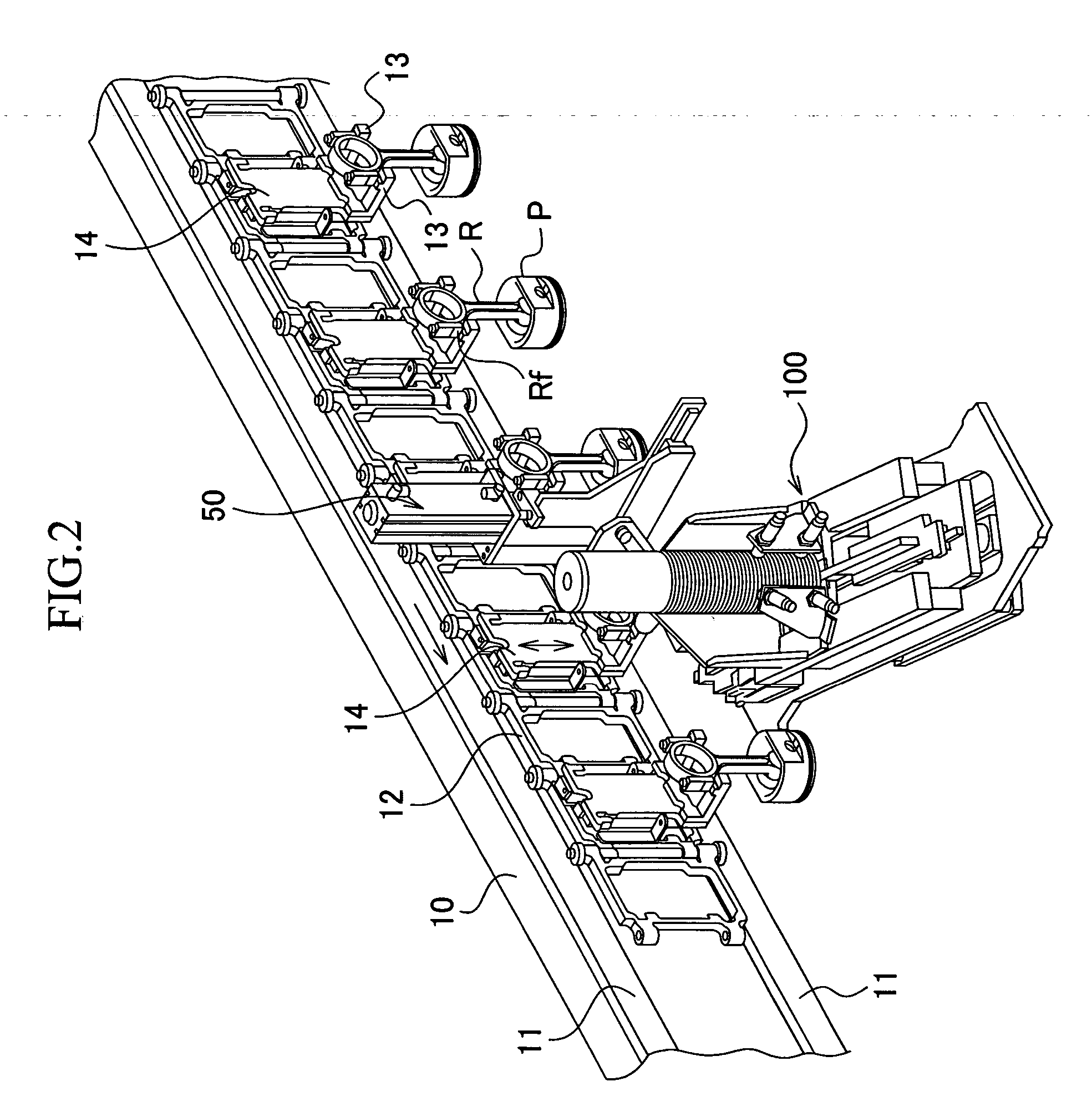
[0045] As shown in FIG. 2, a system for installing a piston ring is made up of a frame 10, guide rails 11 disposed to horizontally extend in parallel with the frame 10, a conveyer 12 guided along the guide rails 11, and a piston-ring-installing device 100 that is disposed in a lower area of the conveyer 12 and that is provided integrally with an elevating mechanism 50 raising and lowering a piston to be set at a position whereat a piston ring is fitted onto the piston.

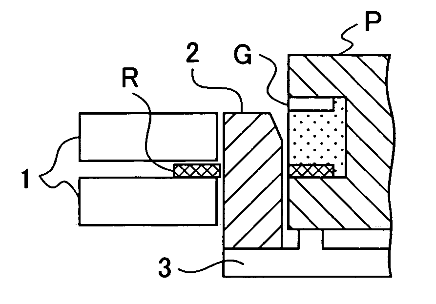
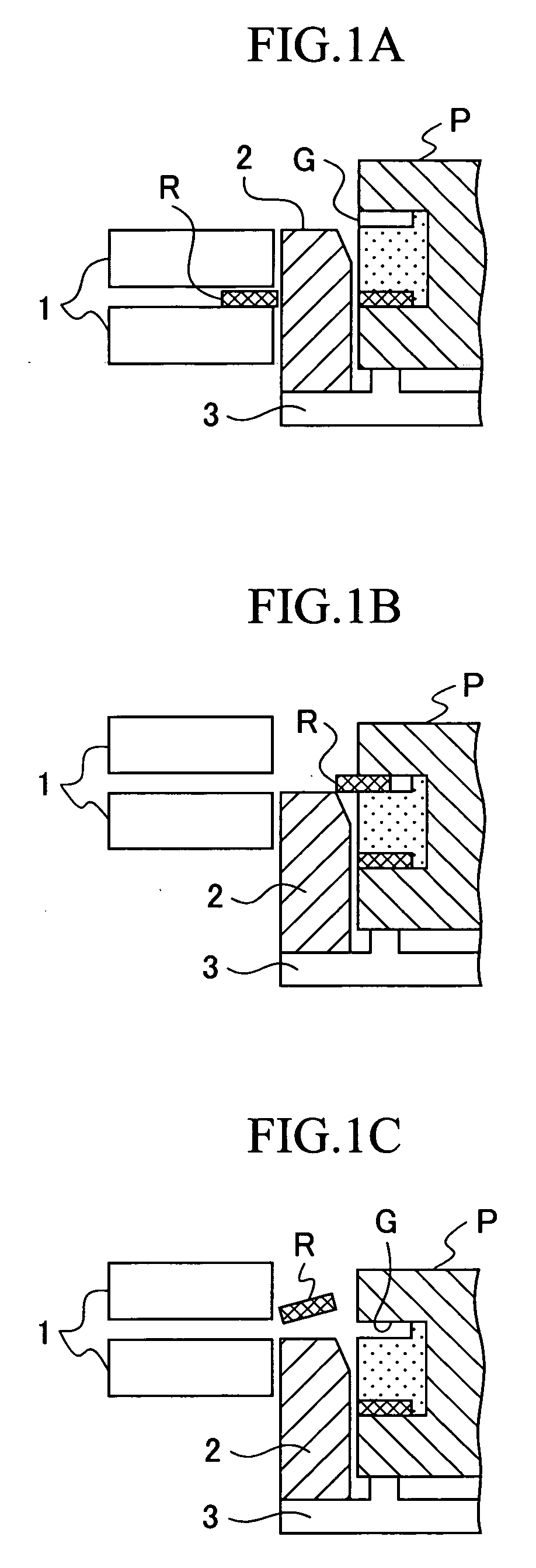
[0046] An oil ring consists of two rail rings and an expander ring, and, in this embodiment, such rail rings are to be installed as piston rings.

[0047] The conveyer 12 is used to convey a piston P, to which a connecting rod R is connected, from a processing step performed on the upstream side in the flow of a sequence of operations to this installing step, and, after completing the installing step, cont...


PUM

PropertyMeasurementUnit
Diameteraaaaaaaaaa

Abstract

The invention provides an installation device and an installation method for a piston ring. The installation device includes an extruding mechanism (110) that horizontally extrudes a piston ring (R) andpositions the piston ring at apredetermined position and, after extruding the piston ring, is driven downwardly in a vertical direction by a predetermined amount and is then returned to a waiting position; a ring holding mechanism (120) that has a guide passage for guiding the extruded piston ring, that is driven so as to move close to and apart from a piston in one direction perpendicular to the extruding direction, and that is capable of defining an insertion hole for inserting the piston in the center area thereof; a ring diameter extending mechanism (130) that extends the diameter of the piston ring, that is driven in a state of entering and leaving the guide passage of the ring holding mechanism, and that is reversely driven to a position for defining a part of the guide passage when the diameter-extended state of the piston ring is released; and a piston holding member (140) that holds the piston at a predetermined position. Thus, the piston ring can be reliably installed.

Description

TECHNICAL FIELD [0001] This invention relates to a device and a method for installing a piston ring onto a piston of an internal combustion engine, and more particularly, to a device and a method for supplying and installing a piston ring from a horizontal direction onto a piston suspended and held downwardly in a vertical direction. BACKGROUND ART [0002] A piston reciprocating in a cylinder bore of an internal combustion engine has a plurality of ring grooves (for example, three ring grooves). For example, two compression rings (chiefly, a first ring that seals a combustion gas and a secondary ring that seals the combustion gas and adjusts a lubricant film) used to prevent a combustion gas from blowing through and an oil ring consisting of a plurality of components (i.e., two rail rings and an expander ring) to adjust the lubricant film are fitted in these ring grooves. A connecting rod is swingably connected to the piston. [0003] As a conventional ring-installing device for instal...

Claims


Application Information

Patent Timeline
IPC IPC(8): B23P21/00B23P19/08
CPCB23P19/088Y10T29/49876Y10T29/4987Y10T29/53065Y10T29/53657Y10T29/53609Y10T29/534Y10T29/53387Y10T29/53365Y10T29/53904Y10T29/49256Y10T29/536
Inventor UEMURA, SHIGERUIKEDA, HIROYASU
Owner HIRATA & CO LTD
Learn More