Retractable airfoil vessel

Inactive Publication Date: 2006-01-31
MARKIE WILLIAM J
View PDF21 Cites 7 Cited by
  • Summary
  • Abstract
  • Description
  • Claims
  • Application Information

AI Technical Summary

Benefits of technology

[0015]This invention accomplishes these and other objectives with a retractable-airfoil vessel having surface-effect wings that are hinged or otherwise attached extendedly to a vessel. The surface-effect wings are extendable to a use mode in proximity to a surface of water at sides of the vessel for surface-effect lift of the vessel at elevated speeds. At low speeds when pleasure cruising or fishing, when stopped for water activities or when adjusting to rough waters and storm conditions, the surface-effect wings provide wide-area buoyance

Problems solved by technology

Hydrofoils have drawbacks related to resis

Method used


Image

  • Retractable airfoil vessel
  • Retractable airfoil vessel
  • Retractable airfoil vessel

Examples


Embodiment Construction

[0025]Listed numerically below with reference to the drawings are terms used to describe features of this invention. These terms and numbers assigned to them designate the same features throughout this description.

[0026]

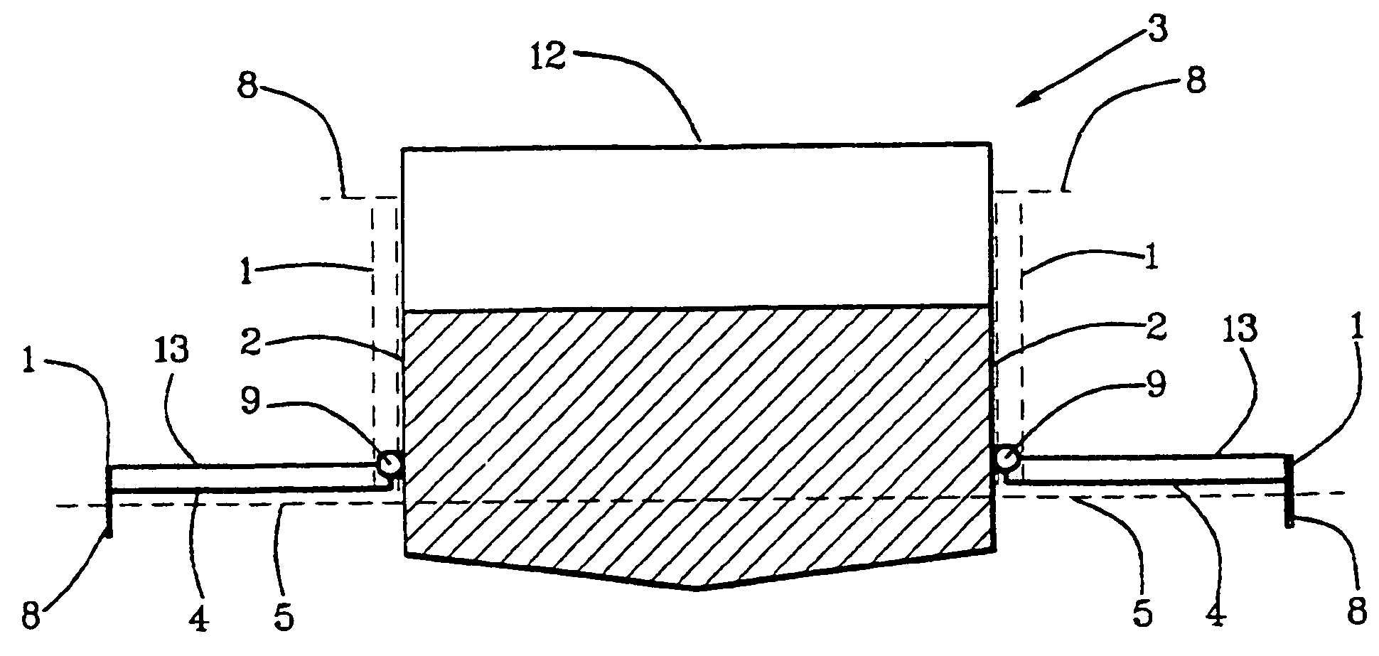
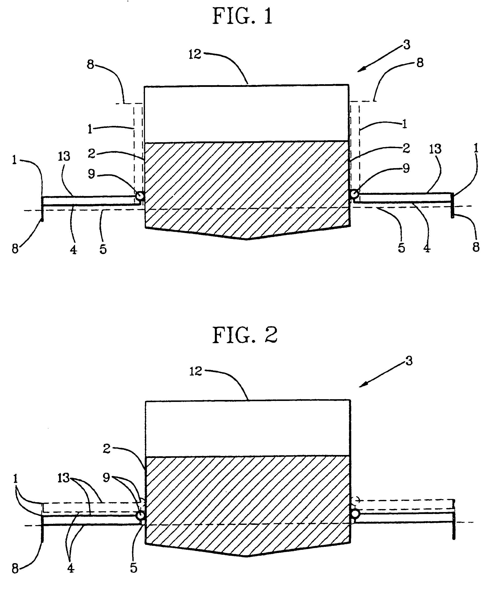
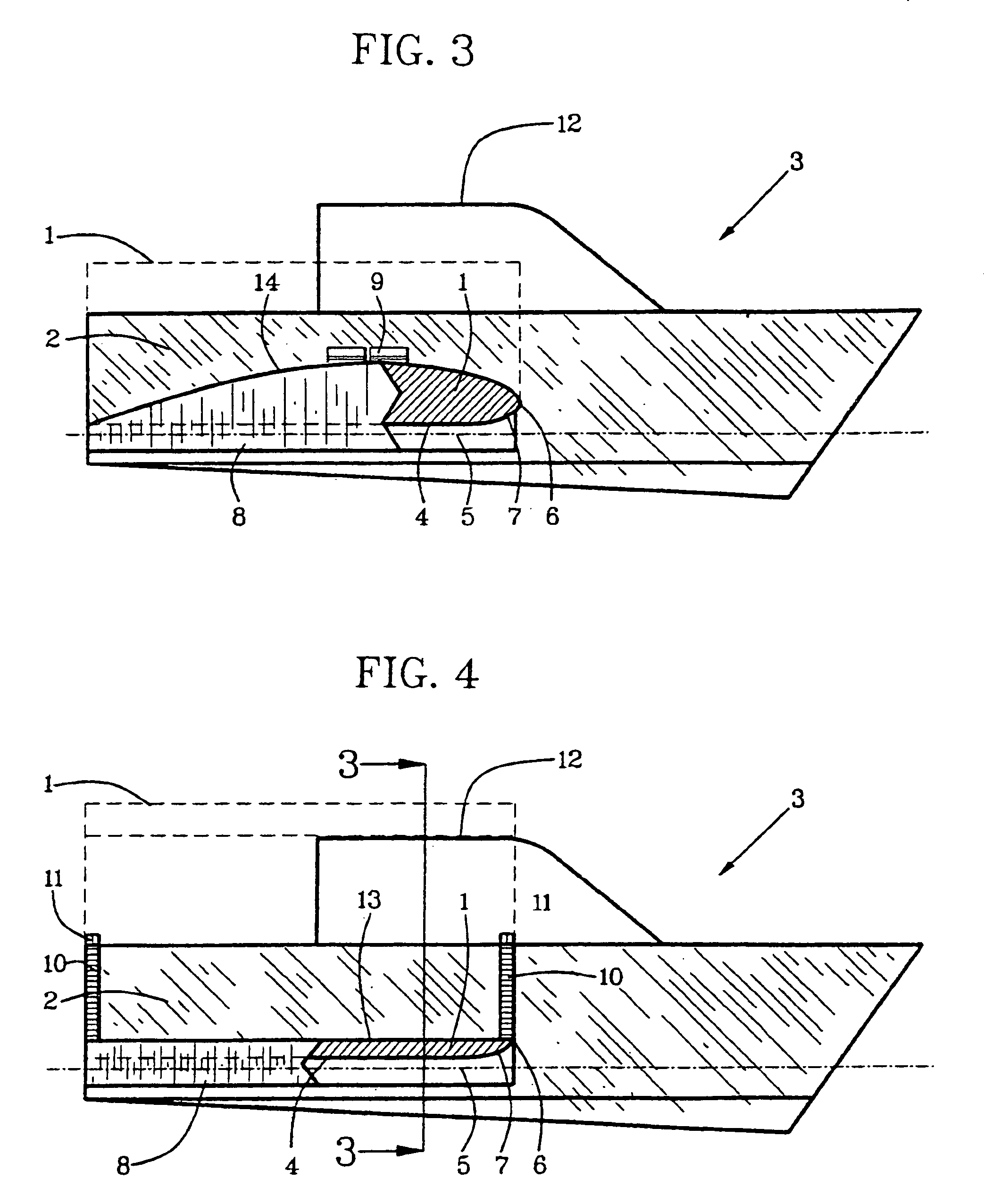
 1.Surface-effect wings 2.Sides 3.Vessel 4.Bottom surface 5.Surface of water 6.Leading edge of a wing 7.Upwardly contoured leading edges 8.End walls 9.Sidewall hinges10.Vessel-top extensions11.Extension hinges12.Top of the vessel13.Top surfaces14.Top-lift surface15.First surface-effect wing16.First side17.Second surface-effect wing18.Second side19.End-wall hinge20.End-wall controls21.Rotational cable22.Worm gear23.Shock Absorber

[0027]Referring to FIGS. 1–2, surface-effect wings 1 are attached extendedly to sides 2 of a vessel 3 having power-vessel structure and motorized power for desired marine use. Motorized power can be inboard, outboard or inboard-outboard with a selection of different shapes and sizes of the vessel 3. A vessel hull shown is intended to represent...


PUM


Abstract

A retractable-airfoil vessel has surface-effect wings (1) that are hinged or otherwise attached extendedly to a vessel (3). The surface-effect wings are extendable to a use mode in proximity to a surface of water (5) at sides (2) of the vessel for surface-effect lift of the vessel at elevated speeds. At low speeds when pleasure cruising or fishing, when stopped for water activities or when adjusting to rough waters and storm conditions, the surface-effect wings can provide wide-area buoyance on water at sides of a center of gravity of the vessel. The best of all worlds, it can be made to ride-out a storm as safely and securely as an anchored buoy and yet have high-speed efficiency, low-speed pleasure cruising and stopping for swimming and marine exploration. Then for docking in vessel slips and for maneuvering in close proximity to docks and harbor structures, the surface-effect wings can be retracted onto the vessel in a non-use mode for non-interference storage and for docked-living shelter.

Description

BACKGROUND OF THE INVENTION[0001]This invention relates to vessels with airfoils and more particularly to a vessel with retractable airfoils that can have both surface-effect lift and airfoil lift to raise the vessel above water for decreasing power relative to speed of propulsion of the vessel and for increasing its smoothness of ride.[0002]Lifting a vessel above water by increasing speed of its propulsion has long been a design objective for overcoming a marine coefficient of increase in power required per length of a water craft with idealized wave-making and wave-breaking proportions of the vessel under five-hundred feet long. Power required per weight of an idealized ship-proportioned displacement hull having a widening front third and a narrowing aft two-thirds of its length at waterline for wave control multiplies approximately four times with decrease of length from five-hundred feet to one-hundred feet long. To compensate for the marine coefficient of impediment from wave-c...

Claims


Application Information

Patent Timeline
IPC IPC(8): B63B1/16B63B1/32
CPCB63B1/322Y02T70/12Y02T70/10
Inventor MARKIE, WILLIAM J.
Owner MARKIE WILLIAM J
Why Eureka
Try Eureka