
Drive mechanism for trailer

a technology of driving mechanism and trailer, which is applied in the field of trailers, can solve the problems that no prior art device discloses the unique features of the present, and achieve the effect of convenient loading and maneuvering of the trailer

Inactive Publication Date: 2006-01-31
SANFORD DANA L +2
View PDF21 Cites 39 Cited by
  • Summary
  • Abstract
  • Description
  • Claims
  • Application Information

AI Technical Summary

Benefits of technology

[0021]An object of the present invention is to provide a means for providing driving and steering power to a trailer upon which a heavy object is placed. A further object of the present invention is to provide the capability for loading an object onto a trailer. Still another object is to provide an electrically powered drive wheel for a trailer having a heavy objected loaded thereon to assist in loading and maneuvering. A further object of the present invention is to enable physically handicapped people or individuals having persistent injuries, such as arthritis, to load heavy objects onto a trailer and to connect a trailer to a towing vehicle.

Problems solved by technology

Devices for loading boats and driving trailers have been described in the prior art; however, none of the prior art devices disclose the unique features of the present.

Method used


Image

  • Drive mechanism for trailer
  • Drive mechanism for trailer
  • Drive mechanism for trailer

Examples


Embodiment Construction

[0082]The following discussion describes in detail one embodiment of the present invention. This discussion should not be construed however, as limiting the invention to those particular embodiments since practitioners skilled in the art will recognize numerous other embodiments as well. For a definition of the complete scope of the invention the reader is directed to the appended claims wherein.

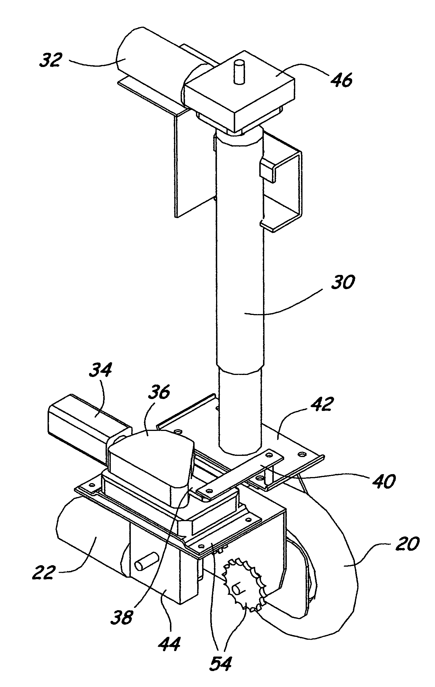
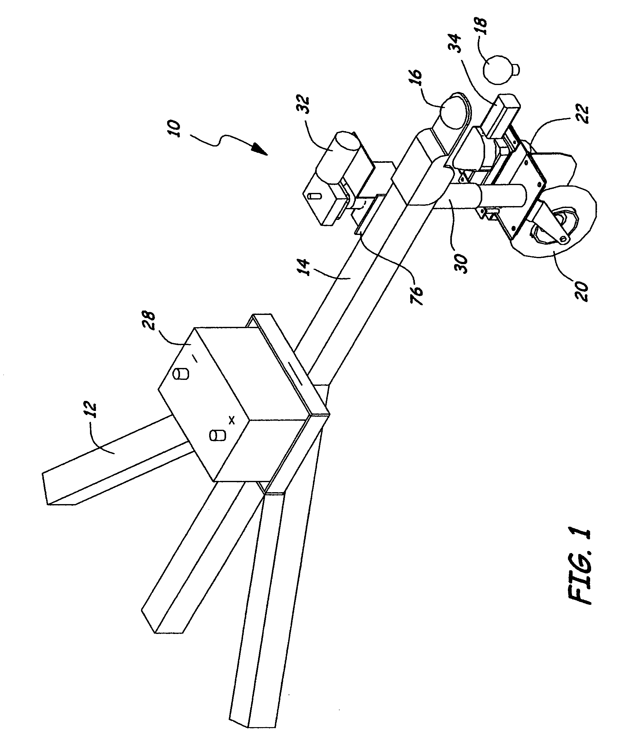
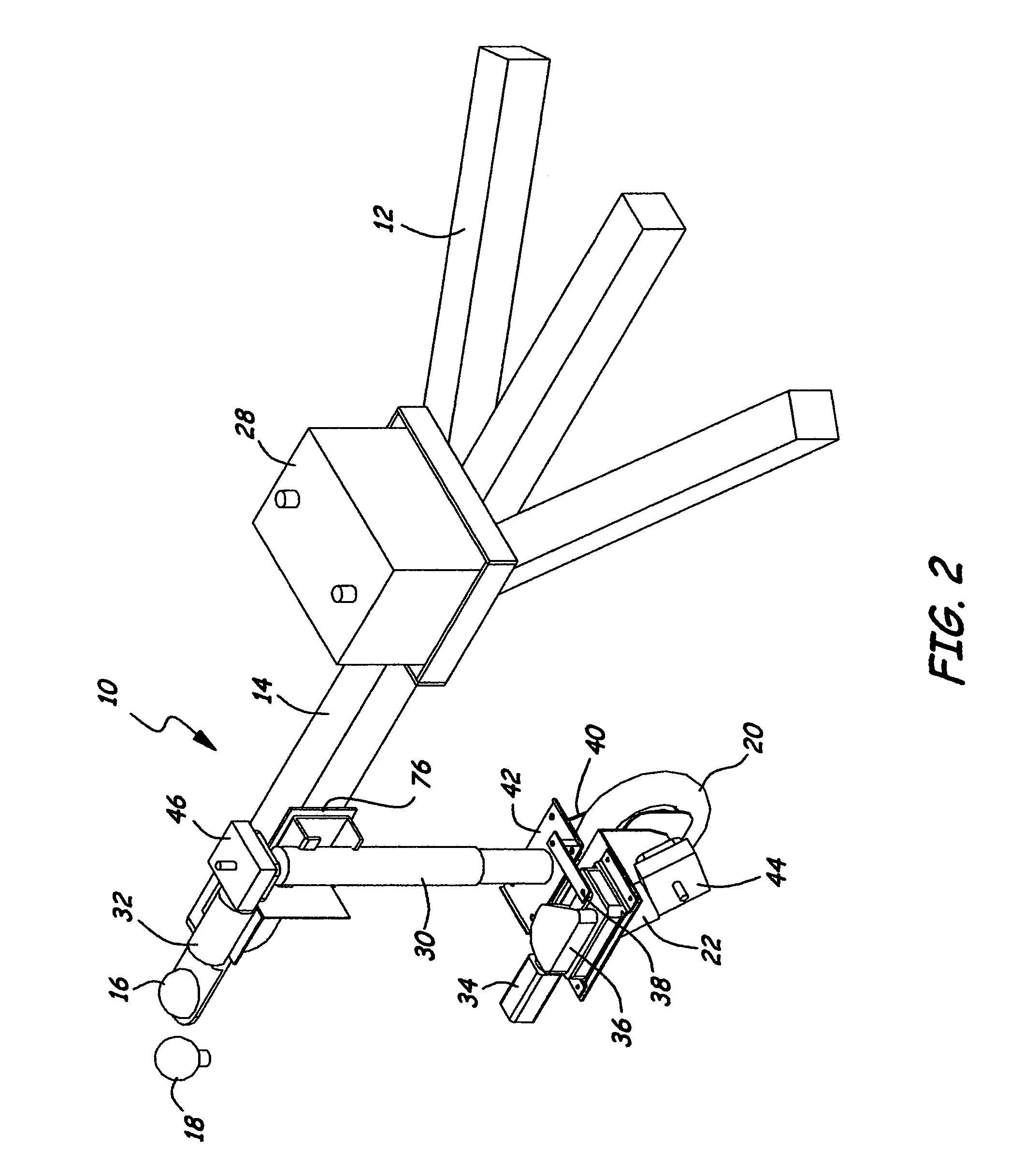
[0083]Turning to FIG. 1, shown therein is the present invention 10 wherein a trailer 12 has the present invention 10 attached at 76 to the tongue 14 thereof similar to a trailer jack. Also shown are the hitch 16 and ball 18 and drive wheel 20. Shown disposed next to the wheel 20 is the drive motor 22, which drive motor is electrically operated and has means for connection to the drive wheel 20 which could be, e.g., a chain and sprocket or a drive shaft and U-joints and would be connected in the standard manner as would be done by one skilled in the art. The battery 28 is shown disposed on tr...


PUM


Abstract

The present invention discloses a drive wheel for placement on the front end of a boat trailer or the like which wheel both drives and steers a trailer into a position where the trailer tong can be connected to the rear end of the towing vehicle. The concept of the present invention may also be applied to other similar vehicles, such as trailers for hauling snowmobiles, woodcutters or water crafts and other heavy objects and possibly for travel trailers.

Description

BACKGROUND OF THE INVENTION[0001]1. Field of the Invention[0002]The present invention relates generally to trailers and, more particularly, is concerned with a trailer having a drive mechanism placed on the tongue thereof.[0003]2. Description of the Prior Art[0004]Devices for loading boats and driving trailers have been described in the prior art; however, none of the prior art devices disclose the unique features of the present.[0005]In U.S. Pat. No. 4,363,590, dated Dec. 14, 1982, Crate disclosed a boat which is supported on a wheeled trailer frame by idler rollers and by powered rollers, of a self-adjusting type, located adjacent the rear end of the trailer frame from which the boar is loaded or unloaded. The powered rollers are driven by drive motors through self-locking gears to effect loading or unloading. The boat is held in a transport position on the trailer frame by the powered rollers through the self-locking gearing when the drive motors are de-energized.[0006]In U.S. Pa...

Claims


Application Information

Patent Timeline
Patent Type & Authority Patents(United States)
IPC IPC(8): B62D51/04
CPCB62D59/04B62D53/0857
Inventor SANFORD, DANA L.ROSS, TERRYBAGLEY, DAVID
Owner SANFORD DANA L
Learn More