Computed tomography image quality phantom

Inactive Publication Date: 2006-01-31
THE BOEING CO
View PDF6 Cites 52 Cited by
  • Summary
  • Abstract
  • Description
  • Claims
  • Application Information

AI Technical Summary

Benefits of technology

[0010]Use of the present invention allows an operator of an EDS to insure that the system maintains a required level of explosive detection at all times.

Problems solved by technology

The existence of attenuating material within the field of view creates image artifacts and ascertains the image resolution and contrast sensitivity simultaneously.

Method used


Image

  • Computed tomography image quality phantom
  • Computed tomography image quality phantom
  • Computed tomography image quality phantom

Examples


Embodiment Construction

[0017]The present invention was developed to accurately and systematically verify the performance of an x-ray computed tomography (CT)-based explosive detection systems (EDS) in common use at U.S. airports. These EDS systems, which commonly are called “scanners,” produce images of x-ray attenuation of the interior of luggage, packages and the like that can be reviewed for evidence of hidden explosives.

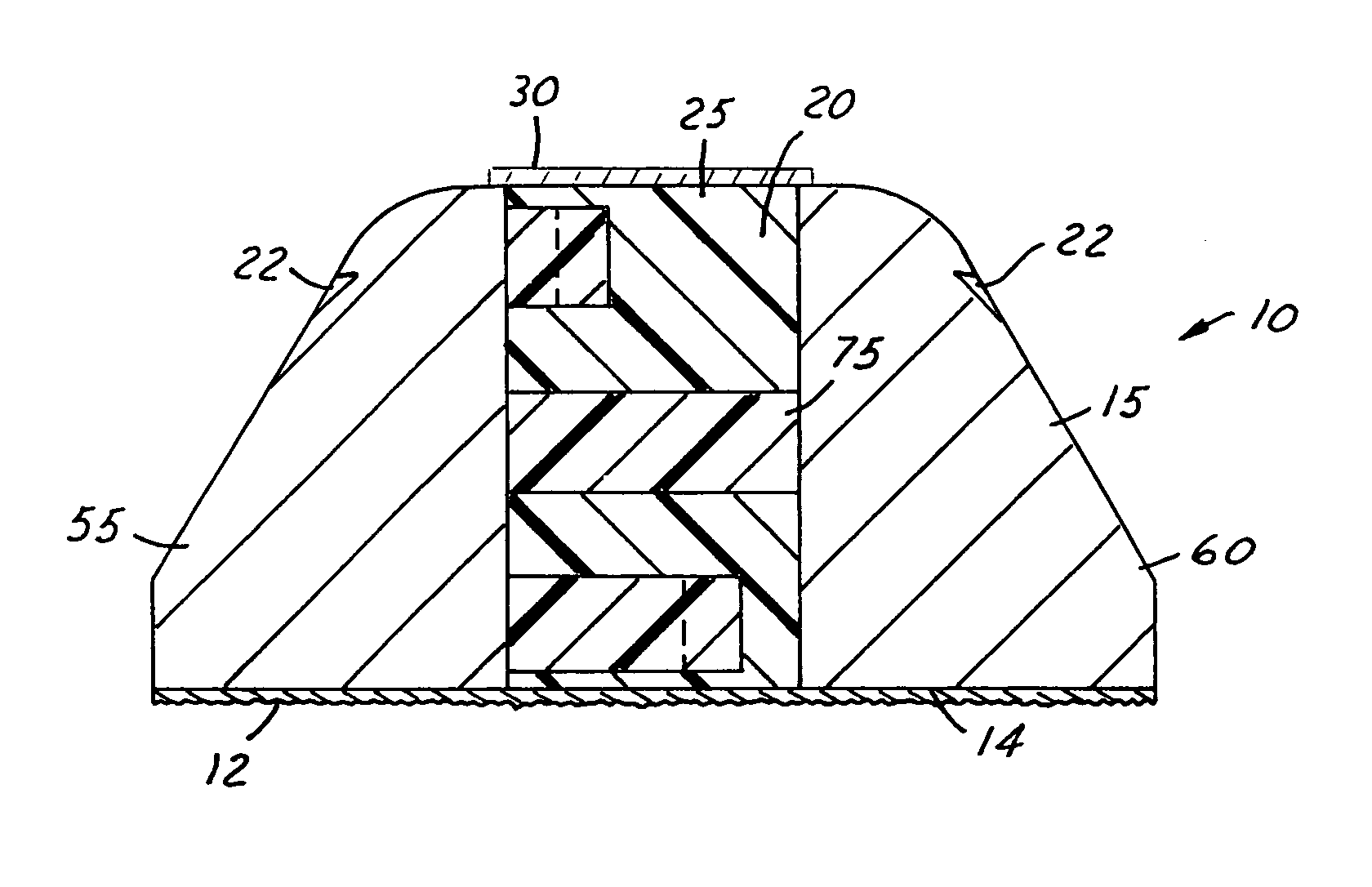
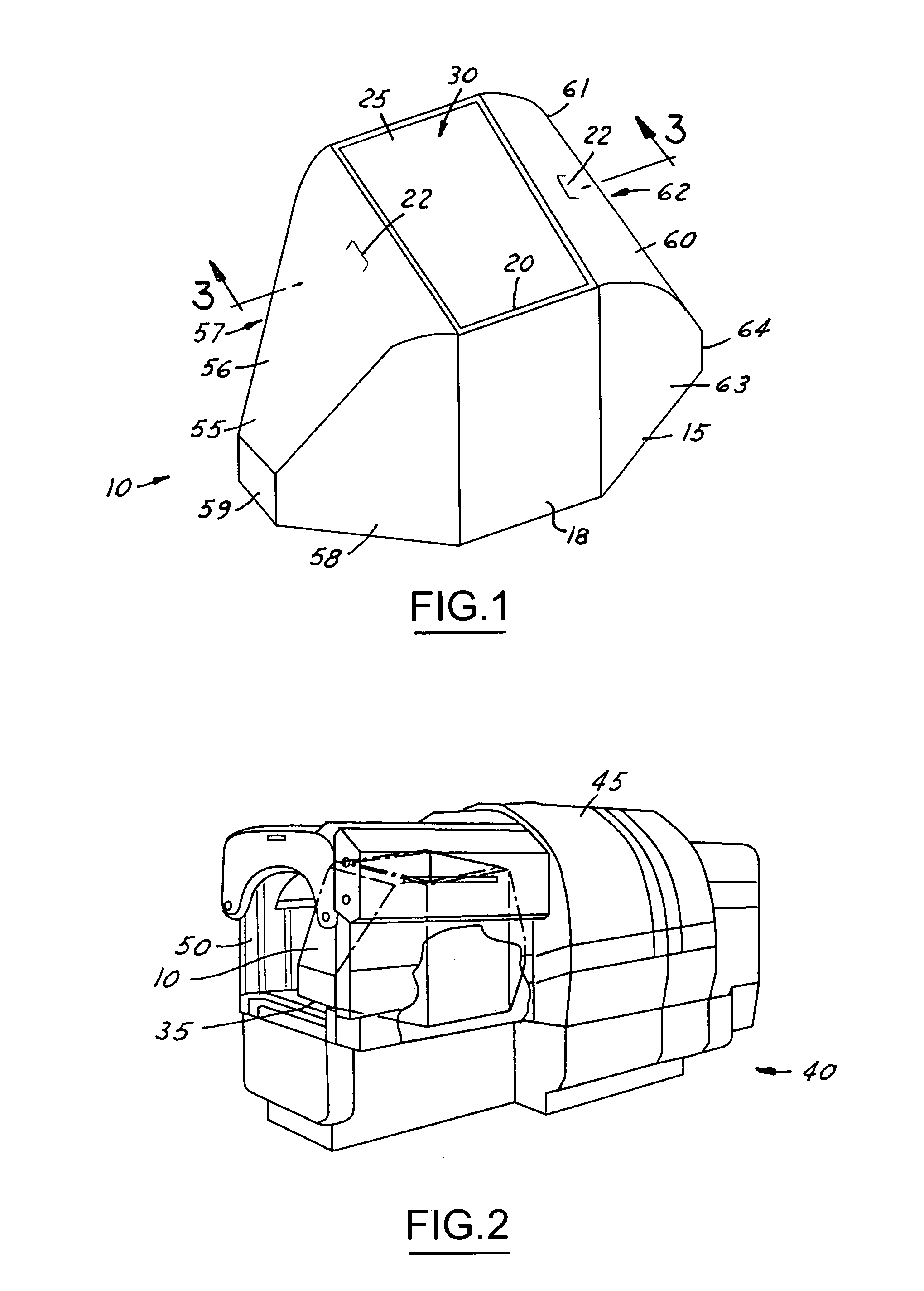
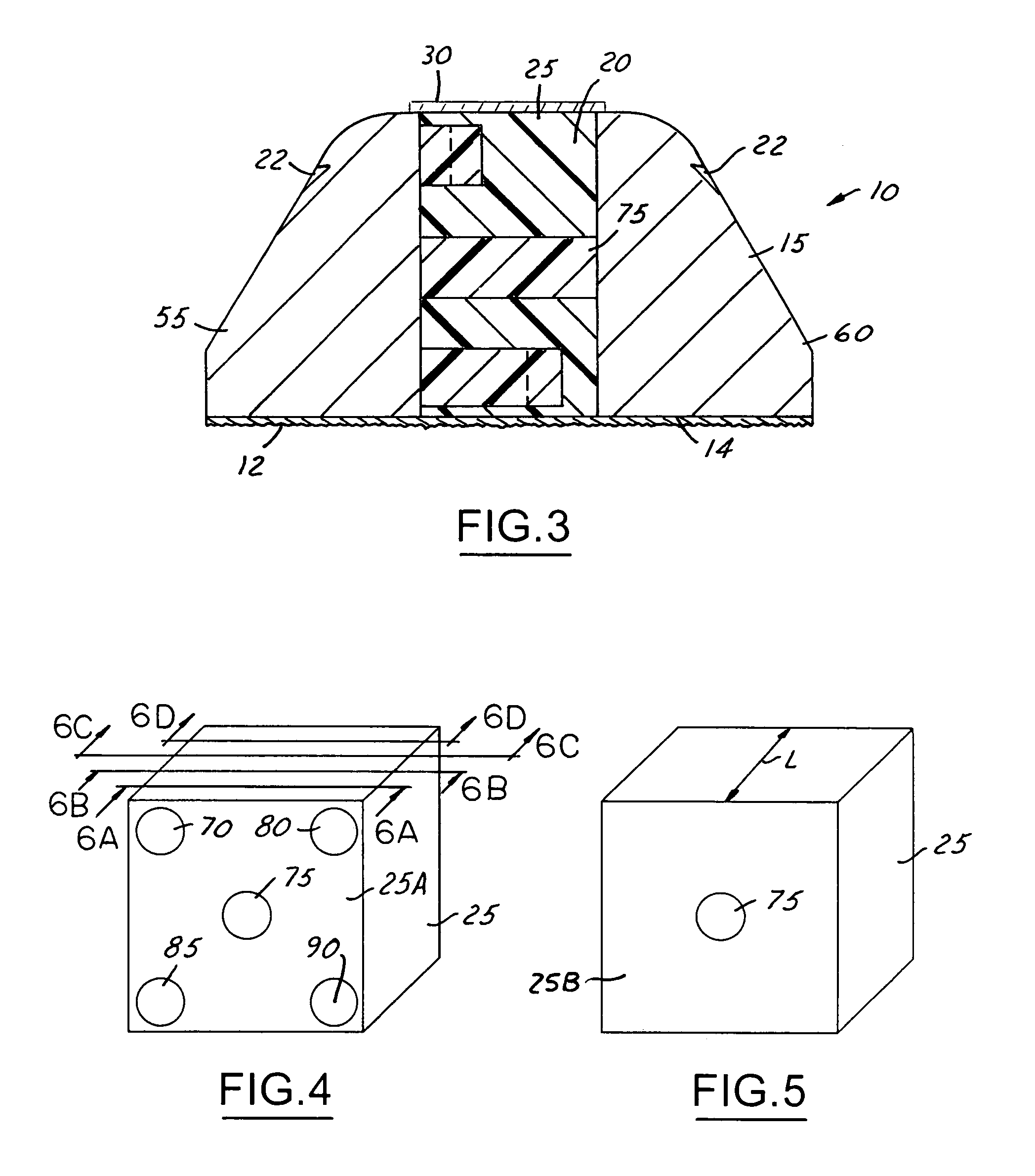
[0018]As shown in FIG. 1, the phantom 10 is shown in a perspective view and includes an exterior housing 15 which has a recess or cavity 20. A core block 25 is positioned in the cavity or recess 20. In addition, a plate or cover member 30 can be positioned on the housing in order to hold the core block 25 firmly in position in the housing 15.

[0019]In use for calibrating EDS machines, the phantom 10 is positioned on the conveyor belt 35 of an airport luggage scanner 40. As is common in airport security systems today, luggage, packages, and other items are positioned on the conveyor belt...


PUM


Abstract

A computed tomography (CT) image quality phantom for use in calibrating explosive detection systems (EDS) at airports. A foam core block containing up to five right cylinder rod members is positioned in a housing member which is adapted to be passed through an airport luggage scanning machine. The rod members are of different lengths in order to create different data slices for analysis. The housing has a lead-in member at least at one end in order to allow passage through an EDS more easily and provide accurate CT calibrating.

Description

GOVERNMENT INTEREST[0001]This invention was made with Government support under Contract No. DTSA 20-03-C-00002 awarded by TSA for Homeland Security. The Government has certain rights in this invention.TECHNICAL FIELD[0002]The present invention relates to devices for calibrating computed tomography (CT) systems, and more particularly to devices for verifying the performance of luggage scanner machines at airports.BACKGROUND OF THE INVENTION[0003]Devices and systems for detecting explosives and other terrorist-type devices are installed in virtually every United States airport. Devices for detecting explosive systems are referred to as Explosive Detection Systems (EDS). These systems are based upon x-ray computed tomography (CT) systems and produce images of x-ray attenuation of the interior of luggage, packages and the like that are reviewed for evidence of hidden explosives. The devices in which the luggage, packages, and other items are passed through are also called “scanners.”[00...

Claims


Application Information

Patent Timeline
Patent Type & Authority Patents(United States)
IPC IPC(8): G01D18/00A61B6/00G01T1/169G01V5/00
CPCG01V5/0008G01T1/169A61B6/583
Inventor GEORGESON, GARY E.NELSON, JAMES M.BOSSI, RICHARD H.
Owner THE BOEING CO
Why Eureka
Try Eureka