Low profile fluid dynamic bearing motor having increased journal span

a low-profile, fluid-dynamic bearing technology, applied in sliding contact bearings, record information storage, instruments, etc., can solve the problem of reducing the dependence on less efficient thrust bearings for angular stiffness, and achieve the effect of improving structural system stiffness, increasing span, and little axial spa

Inactive Publication Date: 2006-01-31
SEAGATE TECH LLC
View PDF13 Cites 78 Cited by
  • Summary
  • Abstract
  • Description
  • Claims
  • Application Information

AI Technical Summary

Benefits of technology

[0009]A stationary shaft design with two plates affixed to or integrated with it at each of its ends supports a rotating hub on fluid bearings between the plates and thereby attaches to both the top cover and base on the outside surfaces of these plates. Connection to both the top cover and base significantly improves structural system stiffness while compromising little axial space due to the shaft-plate configuration. The axial space yielded in turn is used to separate the two journal bearings or lengthen a single journal bearing such that their increased span results in an unusually large moment arm length and subsequent improved bearing angular stiffness which is critical in short height motor designs. This also reduces the dependence on the less efficient thrust bearing(s) for angular stiffness such that they are primarily used to provide less critical axial stability. In a preferred embodiment, a recirculation channel is introduced between the two capillary seals to provide for purging of air from the bearing lubricant to the outside environment and to ensure by its placement that neither seal is drained by a bearing-tolerance-induced net flow. Any combination of conventional and radial capillary seals can be used with this design.

Problems solved by technology

This also reduces the dependence on the less efficient thrust bearing(s) for angular stiffness such that they are primarily used to provide less critical axial stability.

Method used


Image

  • Low profile fluid dynamic bearing motor having increased journal span
  • Low profile fluid dynamic bearing motor having increased journal span
  • Low profile fluid dynamic bearing motor having increased journal span

Examples


Embodiment Construction

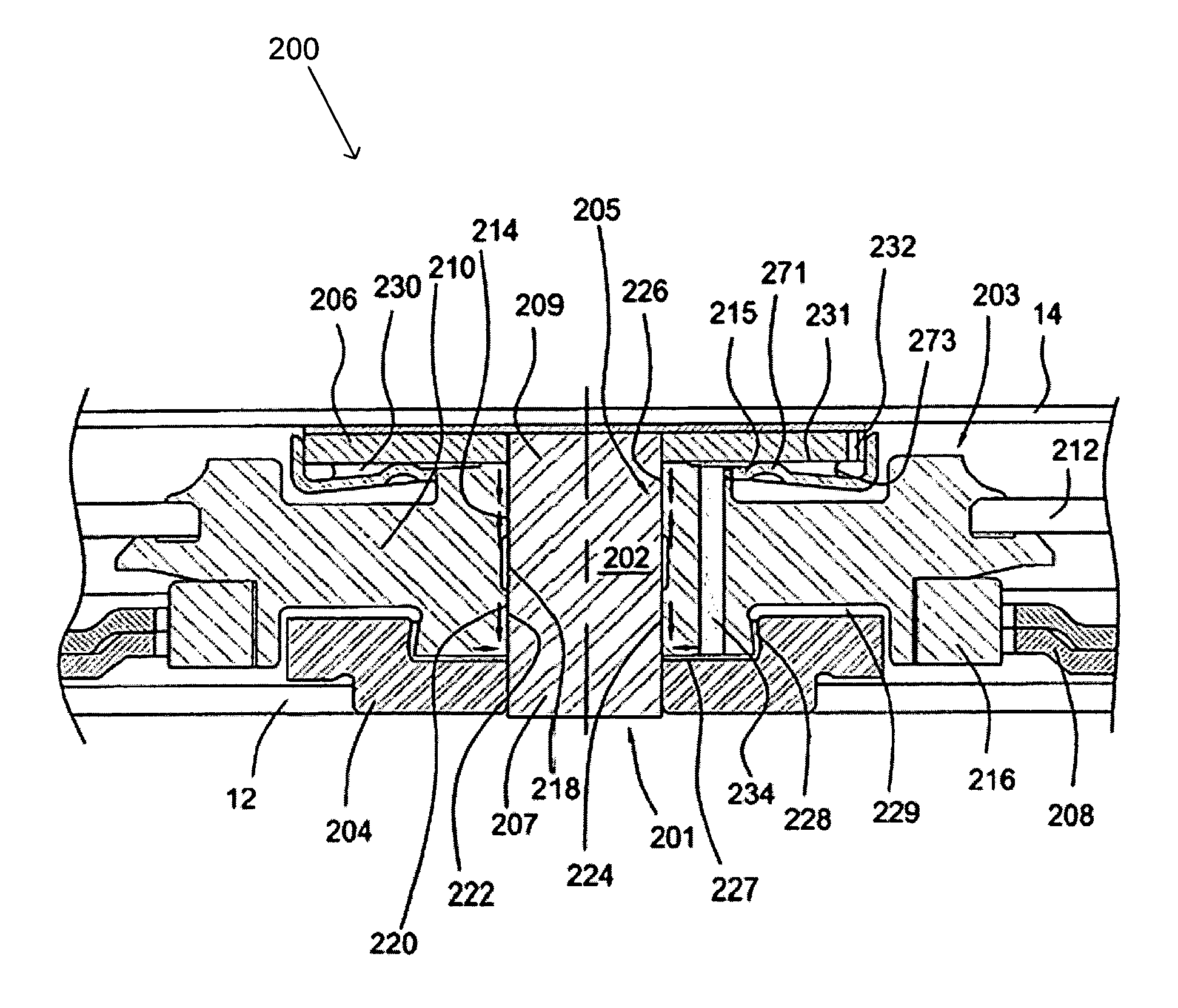
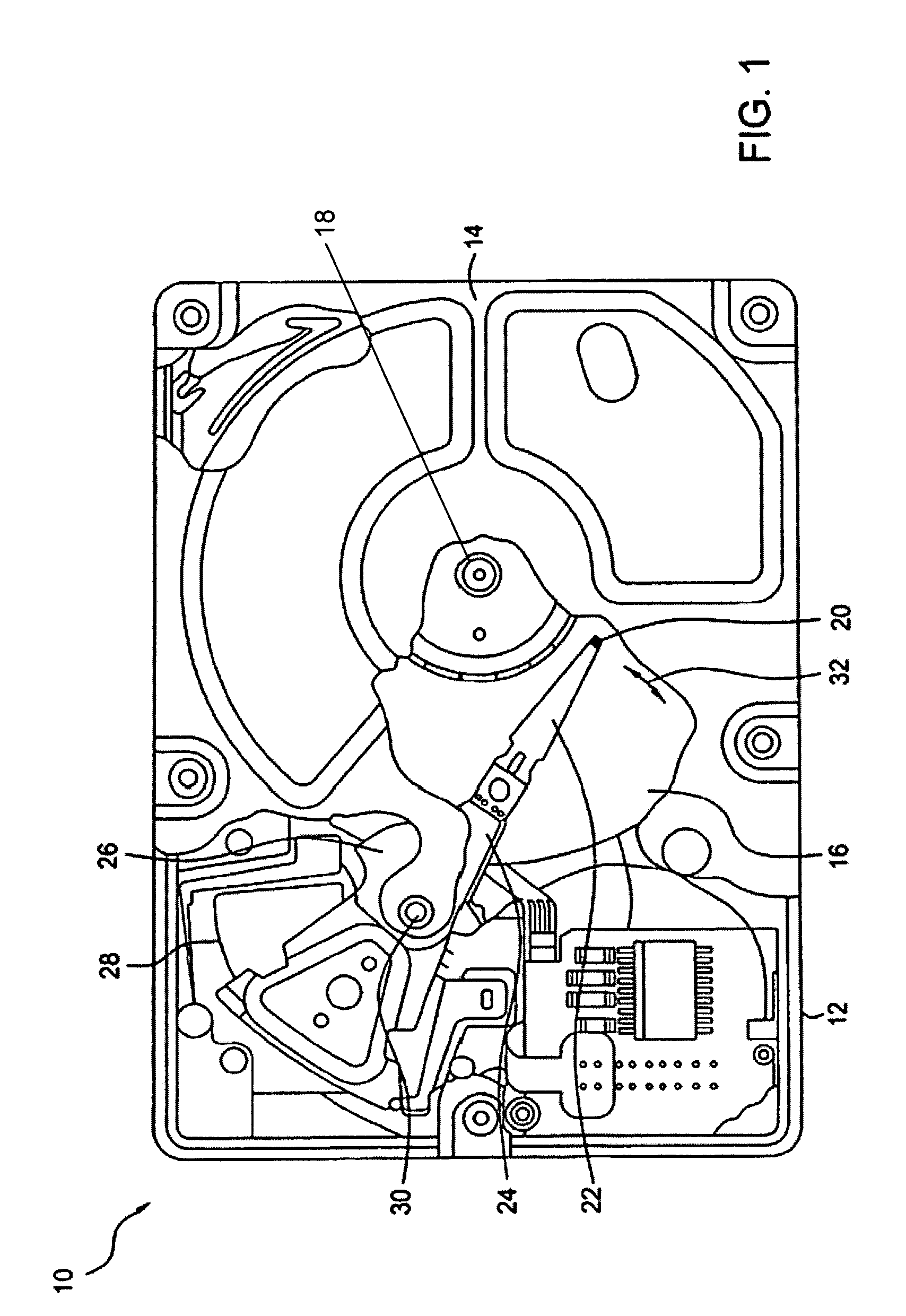
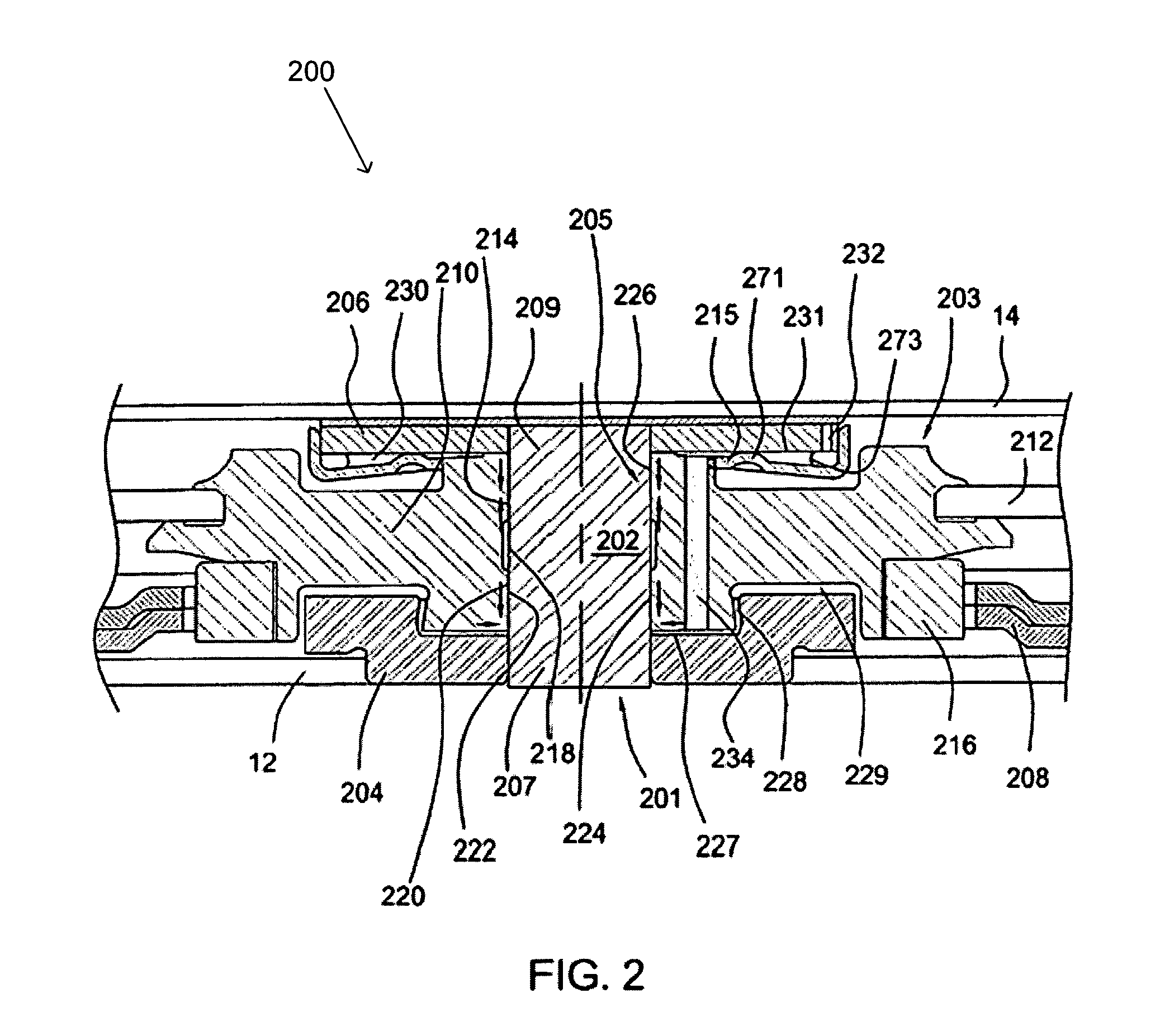
[0016]FIG. 1 depicts a plan view of one embodiment of a disk drive 10 for use with embodiments of the invention. Referring to FIG. 1, the disk drive 10 includes a housing base 12 and a top cover plate 14. The housing base 12 is combined with cover plate 14 to form a sealed environment to protect the internal components from contamination by elements outside the sealed environment. The base and cover plate arrangement shown in FIG. 1 is well known in the industry; however, other arrangements of the housing components have frequently been used, and aspects of the invention are not limited by the particular configuration of the disk drive housing. Disk drive 10 further includes a disk pack 16 that is mounted on a hub 202 (see FIG. 2) for rotation on a spindle motor (not shown) by a disk clamp 18. Disk pack 16 includes one or more of individual disks that are mounted for co-rotation about a central axis. Each disk surface has an associated read / write head 20 that is mounted to the disk ...


PUM

PropertyMeasurementUnit
radiiaaaaaaaaaa
relative rotationaaaaaaaaaa
axial bias forceaaaaaaaaaa

Abstract

A fluid dynamic bearing motor is described. In one embodiment, the fluid dynamic bearing motor includes a stationary shaft having a first end coupled to a first plate and a second end coupled to a second plate. The motor also includes a hub that is configured to rotate relative to the shaft. A fluid dynamic journal bearing, disposed between the shaft and the hub, radially supports the relative rotation of the shaft. The motor further includes a first seal, which is defined in part by the first plate and is disposed radially outboard of the journal bearing, and a second seal, which is defined in part by the second plate and is disposed radially outboard of the journal bearing.

Description

CROSS REFERENCE TO RELATED APPLICATIONS[0001]This application claims the priority of U.S. Provisional Application Ser. No. 60 / 424,226, filed Nov. 5, 2002 by Aiello et al. (entitled “Large Journal Span Fluid Dynamic Bearing Motor”), which is herein incorporated by reference.FIELD OF THE INVENTION[0002]The present invention relates generally to fluid dynamic bearing motors, and relates more specifically to small form factor fluid dynamic bearing motors having limited journal spans.BACKGROUND OF THE INVENTION[0003]Disk drives are capable of storing large amounts of digital data in a relatively small area. Disk drives store information on one or more recording media, which conventionally take the form of circular storage disks (e.g. media) having a plurality of concentric circular recording tracks. A typical disk drive has one or more disks for storing information. This information is written to and read from the disks using read / write heads mounted on actuator arms that are moved from ...

Claims


Application Information

Patent Timeline
Patent Type & Authority Patents(United States)
IPC IPC(8): F16C32/06F16C17/26F16C33/74G11B19/20
CPCF16C33/107G11B19/2018F16C41/008F16C17/107F16C33/745F16C2370/12
Inventor AIELLO, ANTHONY JOSEPHFLORES, PACO GREGORKHURRAM, ALIKLOEPPEL, KLAUS DIETER
Owner SEAGATE TECH LLC
Why Eureka
Try Eureka