Separably joined relationship between adjoining wipes

a technology of joining relationship and adjoining wipes, applied in the direction of identification means, instruments, seals, etc., can solve the problems of not being undesirable, causing a wipe to fall back, etc., and achieve the effect of reducing the likelihood of wipe fallback, improving dispensing, and being more cost-effective and reliabl

Inactive Publication Date: 2006-01-31
KIMBERLY-CLARK WORLDWIDE INC
View PDF32 Cites 26 Cited by
  • Summary
  • Abstract
  • Description
  • Claims
  • Application Information

AI Technical Summary

Benefits of technology

[0004]In response to the difficulties and problems discussed above, for example, a new relationship between two adjacent sheets or wipes, enabling improved dispensing, and which may be more cost effective and reliable (e.g., reducing the likelihood of wipe fallback and / or reducing the likelihood of multiple wipes dispensing undesirably), has been invented. For example, dispensing can be improved or made easier when a wipe is ready for dispensing upon the opening of a resealable wipes dispenser after the initial opening of the dispenser and use of a first wipe in a plurality of wipes. That is, a portion of the wipe is positioned in a restrictive orifice of the dispenser sufficiently protruding so a user can readily grasp the same and remove the entire individual wipe without premature tearing or non-dispensing of the top wipe. As another example, “wipe fallback” can occur when a leading wipe in a plurality of wipes separates completely from a following or trailing wipe prematurely, i.e., before a sufficient portion of the following wipe is positioned within the dispenser orifice to remain there for later dispensing after the leading wipe is fully separated or disjointed from the trailing wipe outside the dispenser. In such a fallback situation, the following wipe would need to be re-threaded through the dispensing orifice when its dispensing is next desired. This may not be undesirable if done intentionally, i.e., if maintaining a maximum moisture level for the sheets is desired, e.g., for wet wipes, and if the dispensing orifice is designed to easily accommodate reach-in retrieval of the next sheet. As yet another example, “multiple wipes” dispensing can occur when a leading individual wipe in a plurality of wipes does not timely separate completely from a following individual wipe while the following wipe is still at least partially maintained in the dispensing orifice, i.e., the following wipe dispenses completely out of the dispenser with the leading wipe causing two (or more) wipes to dispense substantially simultaneously. This can be desirable when two (or more) wipes are needed, but if only one is desired, then this is not preferred.

Problems solved by technology

As another example, “wipe fallback” can occur when a leading wipe in a plurality of wipes separates completely from a following or trailing wipe prematurely, i.e., before a sufficient portion of the following wipe is positioned within the dispenser orifice to remain there for later dispensing after the leading wipe is fully separated or disjointed from the trailing wipe outside the dispenser.
This may not be undesirable if done intentionally, i.e., if maintaining a maximum moisture level for the sheets is desired, e.g., for wet wipes, and if the dispensing orifice is designed to easily accommodate reach-in retrieval of the next sheet.

Method used


Image

  • Separably joined relationship between adjoining wipes
  • Separably joined relationship between adjoining wipes
  • Separably joined relationship between adjoining wipes

Examples


Embodiment Construction

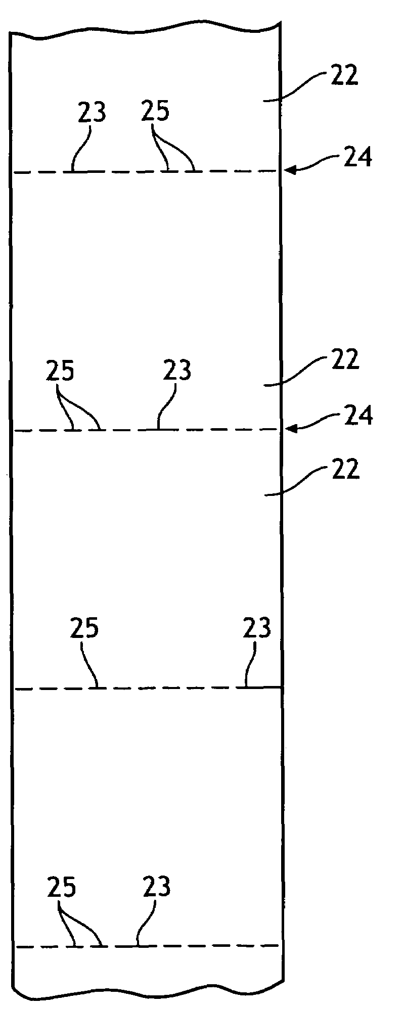
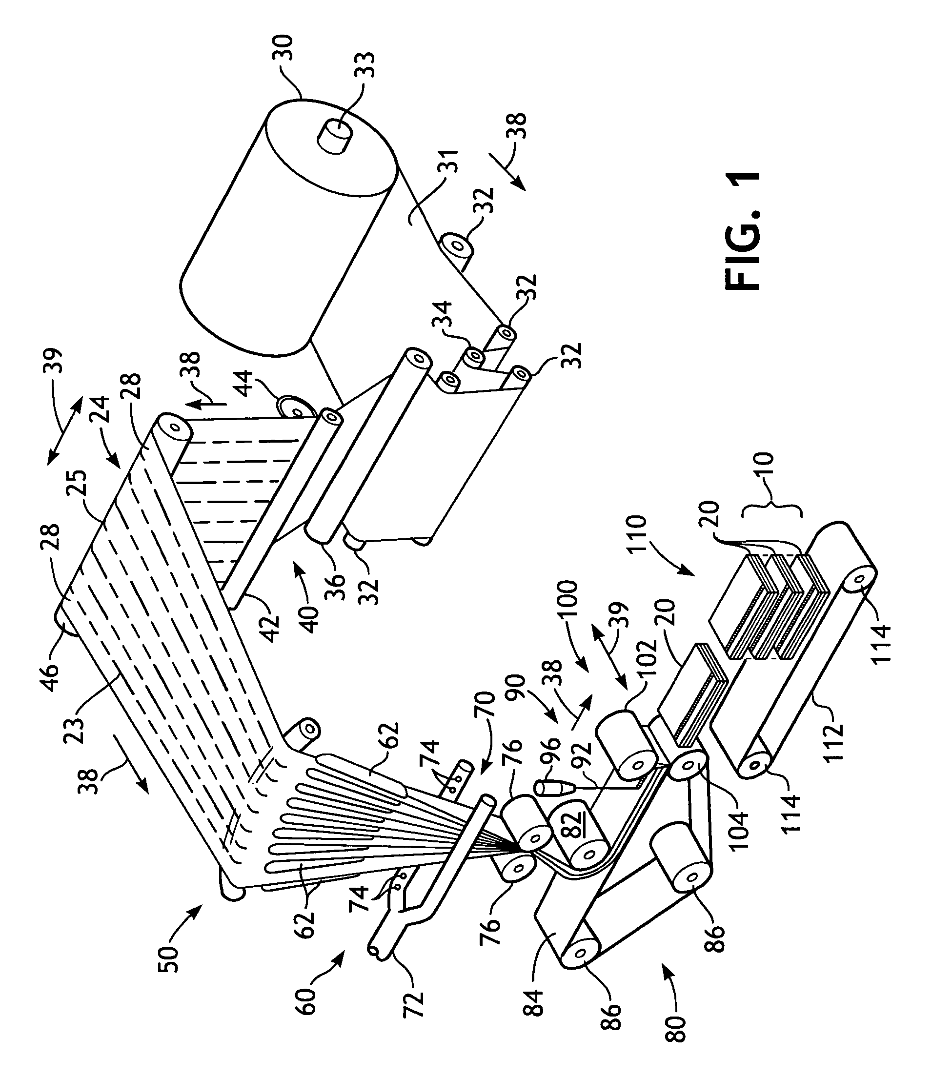
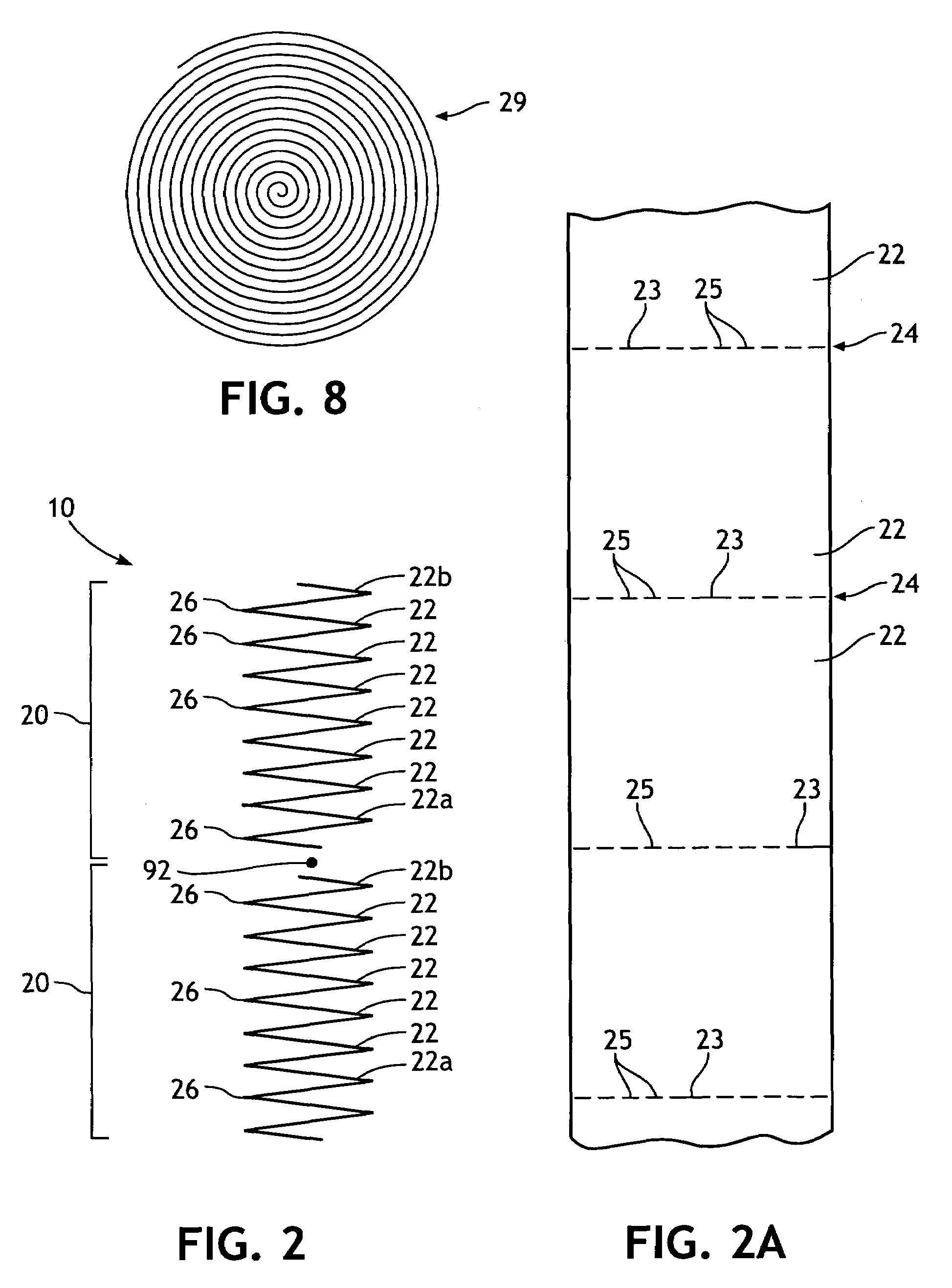
[0028]As representatively illustrated throughout the figures, and for explanation now referring to FIG. 1, there is depicted an apparatus and process for making a stack 10 of a plurality of separably joined wipes from fan folded material. Starting on the right side of FIG. 1, there is a roll 30 of basesheet material 31. The roll can be supported by a roll support 33. The material is fed from the roll 30 through a series of advancing rollers such as idler rollers 32 and dancer roller 34. From there the web of material 31 travels to a slitter assembly 40. The slitter assembly can include an anvil roller 42 and slitting blades 44 that form weakened lines 24 (e.g., perforated slitting blades that thereby form perforations 25 and 23) in the sheet as it travels in the machine direction 38 through the slitting assembly. As a result of traveling through the slitting assembly, the web is formed into a plurality of panels 28 joined to adjacent panels along the plurality of weakened lines 24. ...


PUM

PropertyMeasurementUnit
cut lengthaaaaaaaaaa
widthaaaaaaaaaa

Abstract

The invention relates to a group of wipes. The group of wipes includes at least three wipes separably joined together, each wipe separable joined to each adjacent wipe by a weakened line. Each weakened line includes a plurality of first-type weakened zones and at least one second-type weakened zone. The second-type weakened zone has a length that is at least 1.5 times a length of the first-type weakened zone and the second-type weakened zone is randomly positioned along the weakened line such that no two consecutive weakened lines have the second-type weakened zone in the same position relative to opposite ends of consecutive weakened lines.

Description

BACKGROUND OF THE INVENTION[0001]Wipes have been made from a variety of materials which can be dry or wet when used. Wet wipes can be moistened with a variety of suitable wiping solutions. Typically, wet wipes have been stacked in a container in either a folded or unfolded configuration. For example, containers of wet wipes have been available wherein each of the wet wipes stacked in the container has been arranged in a folded configuration such as a c-folded, z-folded or quarter-folded configuration as are well known to those skilled in the art. Sometimes the folded wet wipes have also been interfolded with the wet wipes immediately above and below in the stack of wet wipes. In an alternative configuration, the wet wipes have been placed in the container in the form of a continuous web of material which includes perforations to separate the individual wet wipes and which can be wound into a roll. Such wet wipes have been used for baby wipes, hand wipes, household cleaning wipes, in...

Claims


Application Information

Patent Timeline
Patent Type & Authority Patents(United States)
IPC IPC(8): B32B3/10B65H35/02B65H45/08B65H45/22B65H45/24B65H45/28
CPCB65H35/02B65H45/08B65H45/28B65H45/22Y10T428/15
Inventor SOSALLA, GERALD KEITH
Owner KIMBERLY-CLARK WORLDWIDE INC
Why Eureka
Try Eureka