
Strength strand construction for a longitudinal section of a cable

a technology of strength strands and longitudinal sections, which is applied in the direction of cable terminations, insulated conductors, cables, etc., can solve the problems of bca and its components requiring a demanding structure, requiring considerable flexibility, and flexing damage, and the previous attempt to use this approach did not provide a significant improvement over tensile strength and flexing damage, so as to achieve high tensile strength and be easy to us

Inactive Publication Date: 2006-01-31
THE UNITED STATES OF AMERICA AS REPRESENTED BY THE SECRETARY OF THE NAVY
View PDF5 Cites 37 Cited by
  • Summary
  • Abstract
  • Description
  • Claims
  • Application Information

AI Technical Summary

Benefits of technology

The invention provides an apparatus and method for strengthening a buoyant cable antenna (BCA) cable section assembly by using multiple longitudinal non-metallic high tensile strength strands integrated into the assembly. This increases the tensile strength of the assembly, allowing it to withstand higher levels of tension. The strengthening strands are integrated into the assembly using a grip foundation molded and bonded to the cable, with the strands interlacing with the grip foundation's longitudinal grooves. The strengthening strands are then secured to the grip foundation using a self-seizing knot and trimmed to prevent protrusion. Overall, the invention provides higher tensile strength characteristics to the BCA cable section assembly.

Problems solved by technology

When not in use, the BCA is coiled around a small diameter spool in the submarine, requiring considerable flexibility.
When deployed from the submarine, the BCA and its components require a demanding structure due to the substantial stress placed on the BCA.
However, the prior attempt using this approach did not provide a significantly improvement over the tensile strength and flexing damage avoidance capabilities provided by the grip sleeves and grip foundation alone.
Accordingly, there is an unsatisfied need for a cable section assembly of a BCA having an imbedded coaxial cable which has higher tensile strength and flexing damage resistance characteristics than heretofore available by application of the foregoing known prior art, and attempted approach of of improvement, of insertion of a moldingly bonded grip foundation into an open-mesh-sleeve type cable end grip.

Method used


Image

  • Strength strand construction for a longitudinal section of a cable
  • Strength strand construction for a longitudinal section of a cable
  • Strength strand construction for a longitudinal section of a cable

Examples


Embodiment Construction

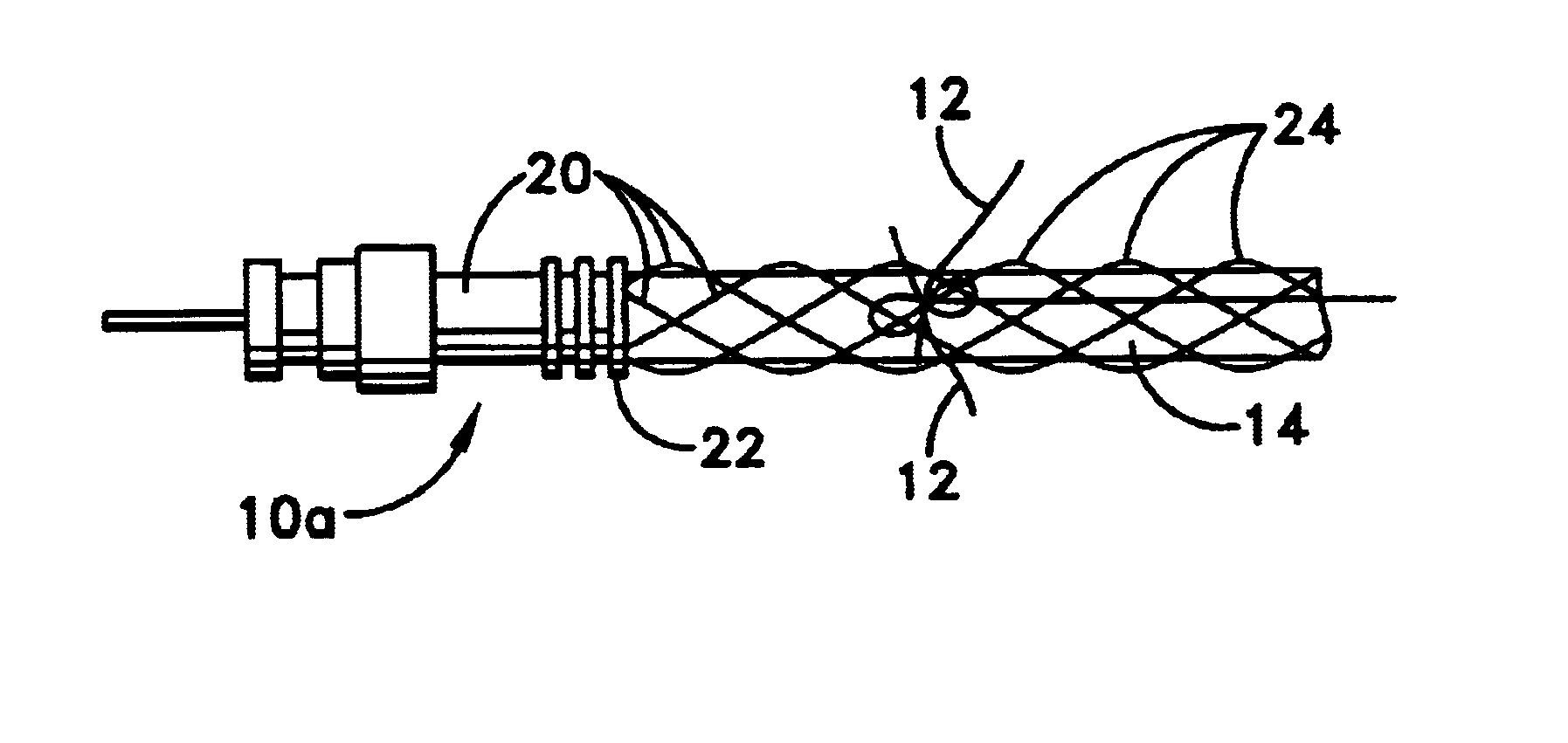
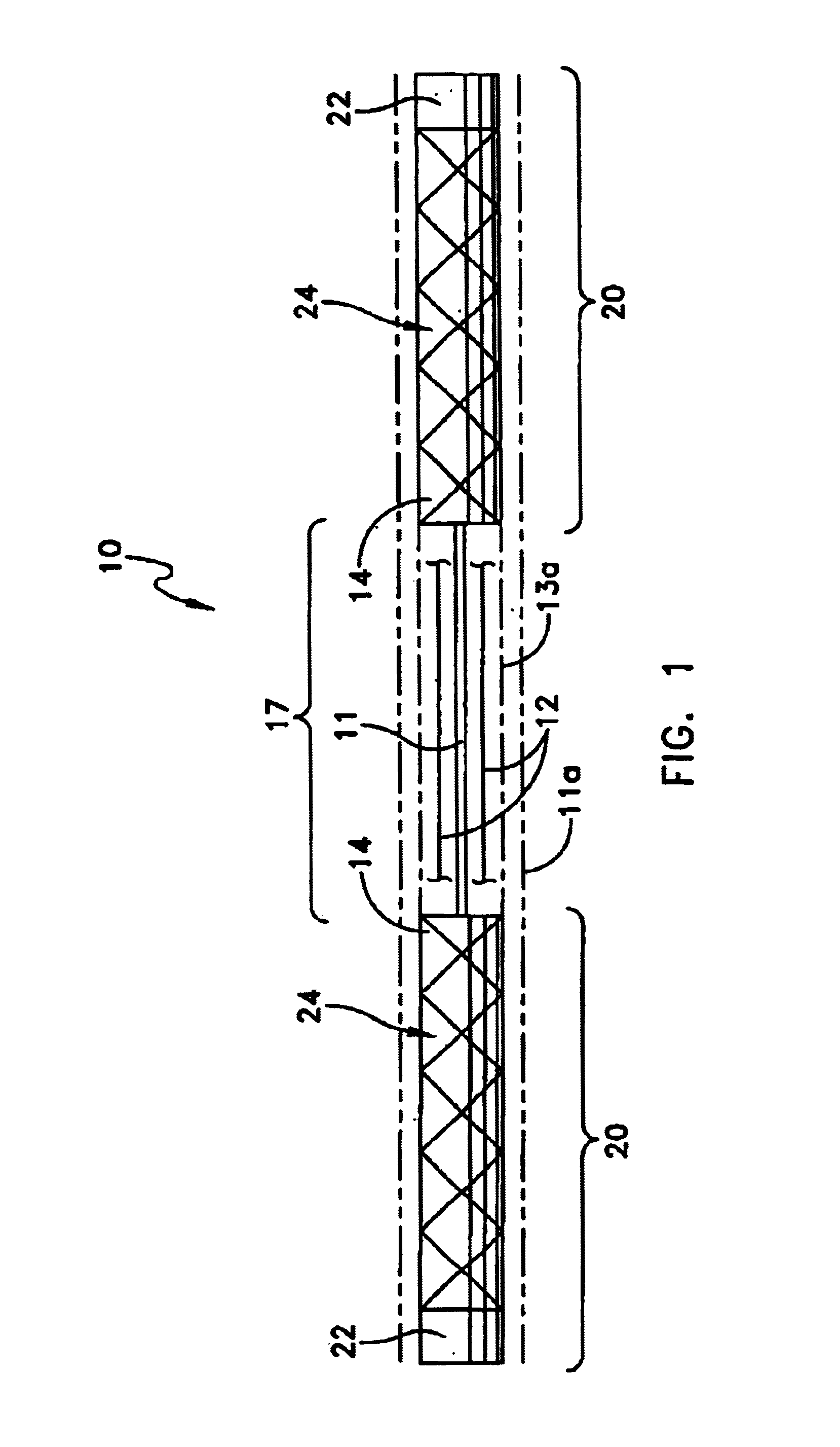
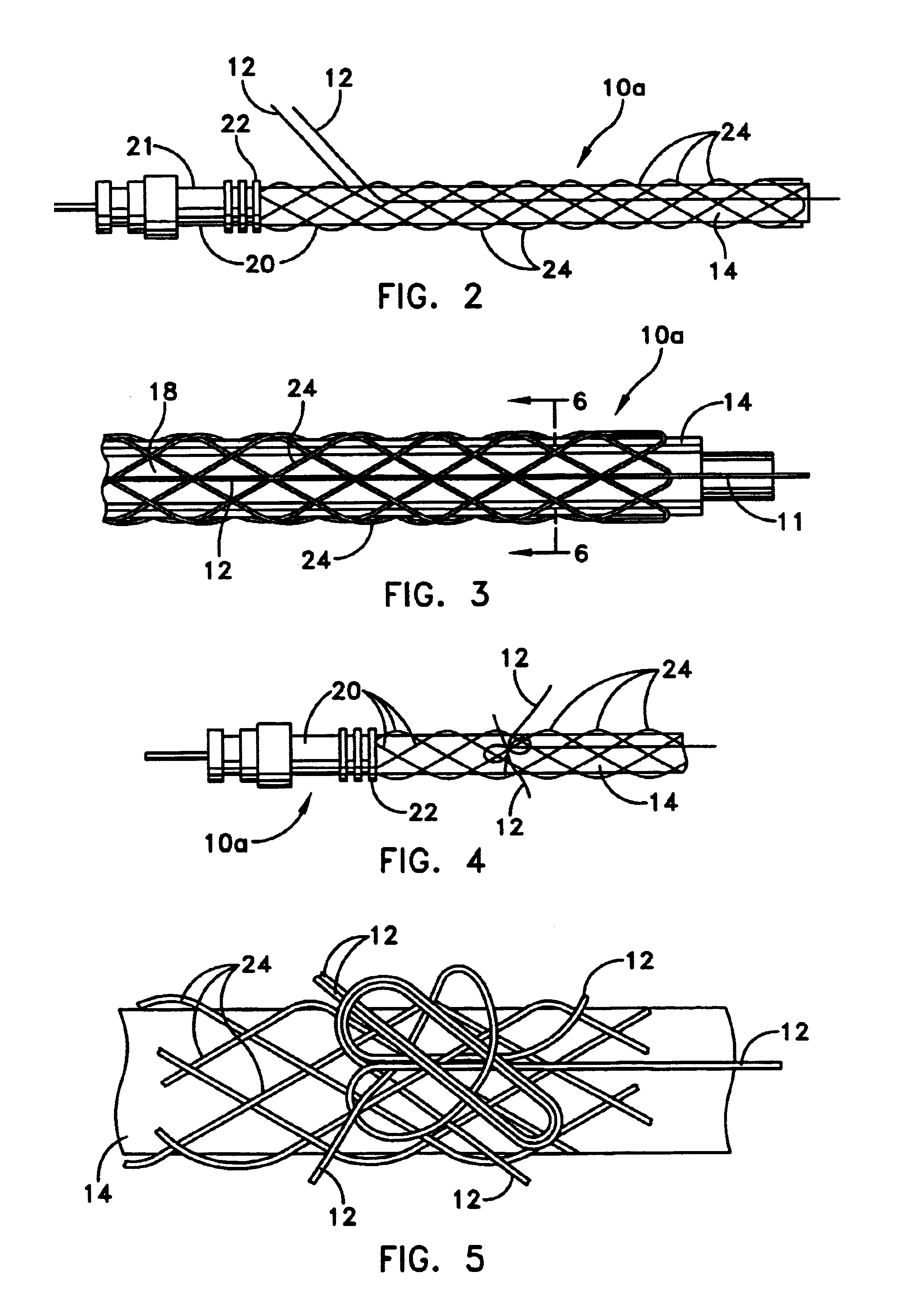
[0022]Reference is now made to the drawings and more particularly to FIGS. 1-4 which depict an illustrative embodiment of the apparatus of the present invention. Referring now more particularly to FIG. 1, this apparatus is a microwave coaxial line cable section assembly 10, which includes the microwave coaxial line 11, sheath 11a (shown by phantom lines) which is for protection against damage to line 11 and for containing an emollient liquid 11b (that serves as a damping medium reduces the magnitude of concussion shock to the assemble which transmitted to line 11). FIGS. 2-4 are directed to an interim manufacturing step subassembly 10a of cable section assembly 10. An application of the embodiment of FIGS. 1-4 involving vulnerability to damage by small diameter capstan mechanisms and by potential high magnitude of shock in heavy sea states is disclosed in the hereinabove identified and incorporated by reference U.S. Pat. No. 6,426,464. Therein cable section assembly may be used as a...


PUM

PropertyMeasurementUnit
depthsaaaaaaaaaa
lengthaaaaaaaaaa
diameteraaaaaaaaaa

Abstract

An assembly including a span of microwave signals flexible coaxial line, or other form energy transmission media, is provided with generally coextensive, non-metallic longitudinal strength strands to render greater tensile strength to the assembly. Marginal axial end sections of a coaxial cable span are potted in respective polyurethane grip foundation having longitudinal grooves. The grip foundations are inserted into an open-mesh-sleeve type cable-end grip device. The strength strands are seated in the grooves and interlaced in and out of the openings in the open-mesh-sleeves of the grip devices. Co-adjacent marginal end portions of the strength strands are bundled beyond the interlacing, and knotted to the open-mesh-sleeves of the grip devices. In forming the knots the bundled marginal end portions of the strength strands are entwined and bound together and with a pair of the crossing strands of the open-mesh-sleeve.

Description

CROSS REFERENCE TO RELATED PATENT APPLICATION[0001]This application is related to a co-patent application entitled OUTER CASING STRUCTURE AND FABRICATION METHOD FOR CABLE SECTIONS AND NAVY BUOYANT ANTENNAS, filed on an even date herewith. This co-pending application is hereby incorporated herein in its entirety.STATEMENT OF GOVERNMENT INTEREST[0002]The invention described herein may be manufactured and used by or for the Government of the United States of America for governmental purposes without payment of any royalties thereon or therefor.BACKGROUND OF THE INVENTION[0003](1) Field of the Invention[0004]The present invention relates to a novel apparatus and method for providing tensile strength to longitudinal sections of cables, including cables in which a linear energy transmission medium has a surrounding arrangement of a damage resistant outer sheath with emollient liquid between the sheath and the transmission medium. It also relates to such providing tensile strength to forms...

Claims


Application Information

Patent Timeline
Patent Type & Authority Patents(United States)
IPC IPC(8): H01B7/00
CPCH01Q1/34
Inventor SPELLMAN, CHARLES D.RODERICK, WALTER J.PORTOFEE, DONALD C.
Owner THE UNITED STATES OF AMERICA AS REPRESENTED BY THE SECRETARY OF THE NAVY
Learn More