Electric ballast

Inactive Publication Date: 2006-01-31
KONINKLIJKE PHILIPS ELECTRONICS NV
View PDF13 Cites 3 Cited by
  • Summary
  • Abstract
  • Description
  • Claims
  • Application Information

AI Technical Summary

Benefits of technology

[0008]A further advantage of the invention is in that both the cover and the coil base may each have a substantially constant wall thickness. This generally leads to a more efficient production cycle in the manufacture of the relevant synthetic resin products in batches on an industrial scale. The coil base of the ballast in accordance with the prior art, however, will exhibit a substantial reduction in wall thickness at least at the location of the folding seams. As a result, there is a substantial spread in the curing time of the synthetic resin.
[0009]In addition, the invention leads to an important efficiency improvement of the coil manufacture in that, in the case of the inventive ballast, after the provision of the coil windings on the coil base, only the single cover has to be provided, two ends of which are connected to each other. Unlike this, in the case of the known ballast, after the provision of the coil windings on the coil base, 6 lamellae must be turned over and at least two of said lamellae must be secured to the base part. This does not only involve a larger number of operations, but also the sequence in which the various lamellae are turned over is to be observed.
[0010]Further, the m

Problems solved by technology

For example, the base part, which serves as a support, may be made of a glass-filled synthetic resin which, on

Method used


Image

  • Electric ballast
  • Electric ballast
  • Electric ballast

Examples


Example

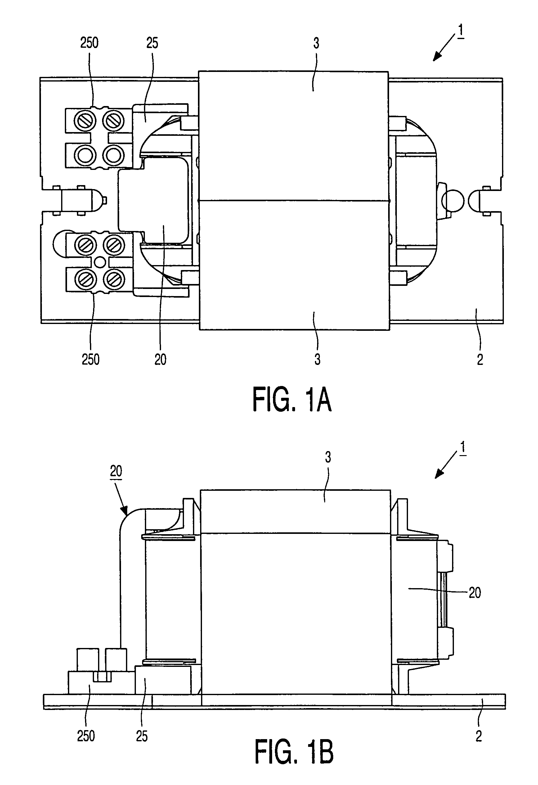
[0019]In FIGS. 1A and 1B, an electric ballast 1 is provided with a housing formed by a cover plate 2 mounted on an external sheet stack 3. A coil incorporated within the ballast is provided with a connection member 250 which connects to an external insulator 25 which forms a part of a cover 20.

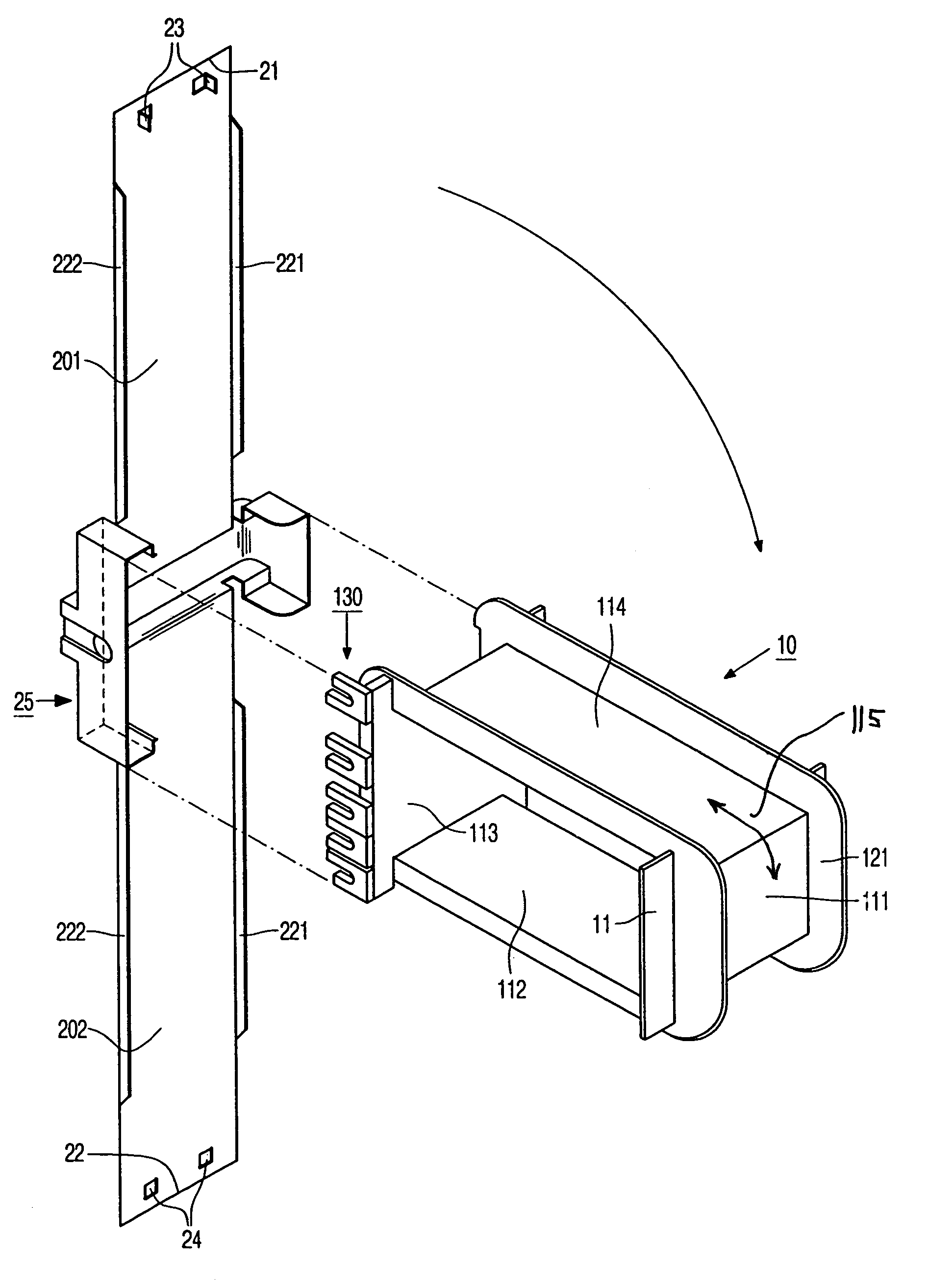
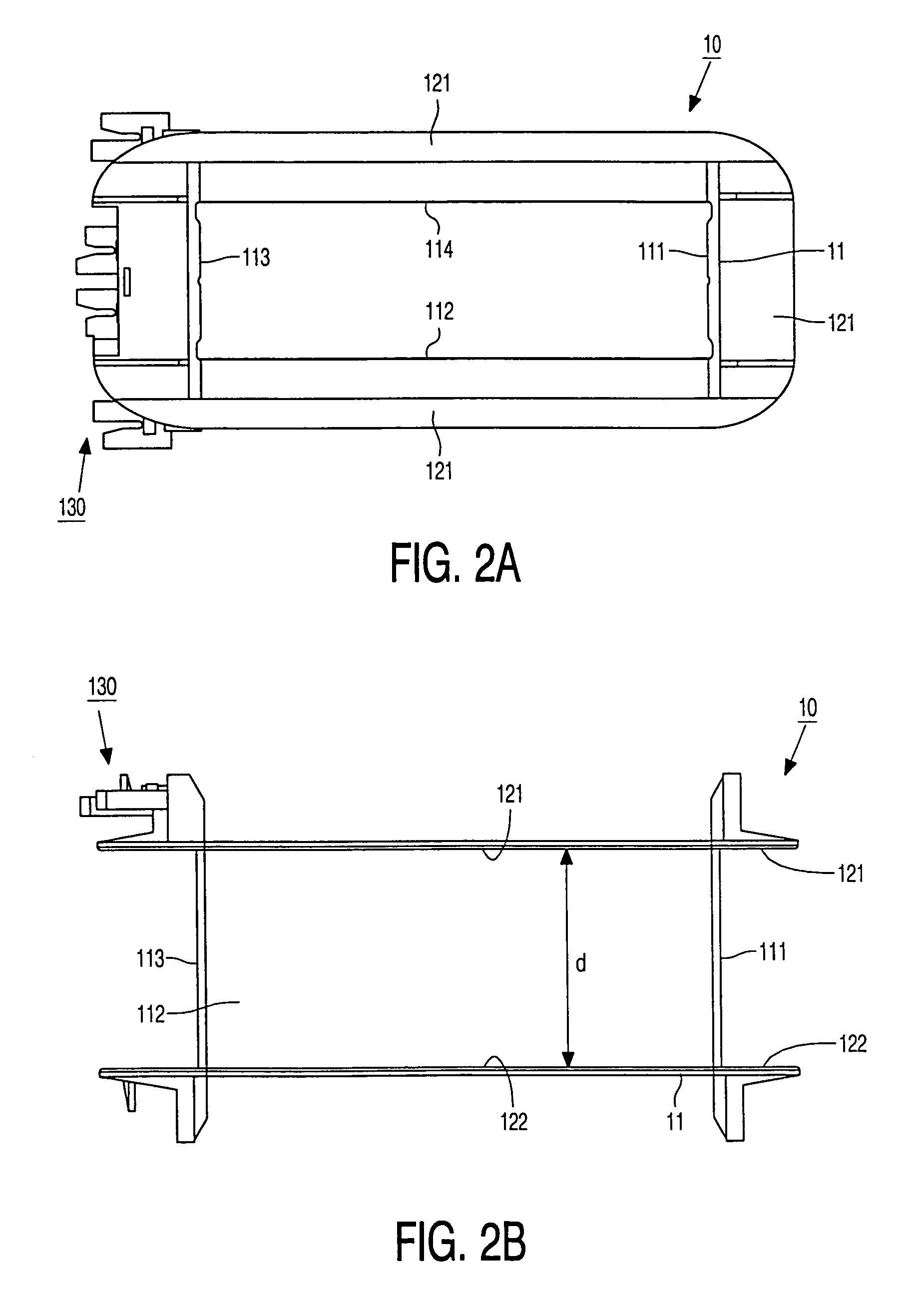
[0020]The coil comprises a synthetic resin coil base 10, shown in FIG. 2. FIG. 2A is a plan view and FIG. 2B a side view of the coil base 10. Said coil base 10 has a box-like base part 11 which comprises four faces 111, 112, 113, 114 which are arranged so as to form a rectangle for accommodating a metal core, for example an iron core, which is not shown. The synthetic resin base part is used to reel up coil windings having a width d. The base part is provided, on either side, with mutually parallel flanges 121, 122 which limit the width d of the coil windings. The coil base comprises a member 130 for forming a connection member 250 for connecting an external electrical connection.

[0021]In FIGS...


PUM


Abstract

An electric ballast 1 is provided with an electric coil with windings having a width d which are wound on a synthetic resin coil base 10 comprising a box-like base part 11 of rectangular shape having four faces 111, 112, 113, 114. The base part is suited to accommodate an iron core of the coil. The base part is provided on either side with mutually parallel flanges 121, 122 which define the width d.
The ballast is provided with a separate, insulating synthetic resin cover which is in one piece and which, when positioned in engagement with the coil base, cooperates therewith to substantially completely enclose the coil windings.

Description

BACKGROUND OF THE INVENTION[0001]1. Field of the Invention[0002]This invention relates to an electric ballast comprising an electric coil with coil windings having a width d which are wound on a synthetic resin coil base including a box-like base part comprising four faces arranged so as to form a rectangle for accommodating a metal core, said base part being provided on either side with mutually parallel flanges limiting the width d of the coil windings.[0003]2. Description of the Related Art[0004]An electric ballast of the type mentioned in the opening paragraph is known from EP-0 018 596. This known ballast can suitably be used, inter alia, as a ballast for an electric discharge lamp. In said known ballast, the coil base comprises lamellae which, after providing the coil windings, are turned over and secured with a free end to the base part so as to completely enclose the coil windings. The base part and the lamellae are made of an insulating synthetic resin and are manufactured ...

Claims


Application Information

Patent Timeline
IPC IPC(8): H01F27/30H01F27/02H01F27/32H01F37/00H01F38/10
CPCH01F38/10H01F27/326
Inventor VALLEN, JACOBUS W.
Owner KONINKLIJKE PHILIPS ELECTRONICS NV
Why Eureka
Try Eureka