
Image pickup apparatus having plural pixels arranged two-dimensionally, and selective addition of different pixel color signals to control spatial color arrangement

a pickup apparatus and two-dimensional arrangement technology, applied in the field of image pickup apparatus, can solve the problems of signal degradation, increased device cost, and a large increase in power consumption, and achieve the effect of ensuring image quality

Inactive Publication Date: 2006-01-31
CANON KK
View PDF13 Cites 121 Cited by
  • Summary
  • Abstract
  • Description
  • Claims
  • Application Information

AI Technical Summary

Benefits of technology

[0012]It is, therefore, one objective of the present invention to provide an image pickup apparatus that can add together a plurality of pixel signals and that can thus obtain a preferable image quality with such the addition.

Problems solved by technology

But when reading is performed at this speed, there is a considerable increase in the consumption of power and signals are degraded by the noise that is produced by the increased power consumption.
Furthermore, device costs are also increased because more image processing memory is required.
In this case, the problem is that the number of pixels in a 4×4 pixel block that are effectively used is reduced to ¼ of the total, and for the full pixel count, is reduced to 1 / 16 of the total.
That is, the use efficiency is greatly deteriorated, and in actuality, such a device is used merely as a monitor.
This process can not be implemented using a CCD (since a CCD employs charge-coupled transmissions, X-Y scan reading is difficult).
In addition, the KTC noise along a vertical signal line is too large to perform the process using a semiconductor switch and a photodiode, so that a preferable S / N ratio can not be obtained.
As is described above, since in the prior art pixel signals are thinned out to be read in every 4×4 pixel block, a satisfactory resolution can not be acquired and a satisfactory S / N ratio can not be obtained.
Therefore, the horizontal addition of signals is easy, while the vertical addition of signals or the oblique addition is difficult.

Method used


Image

  • Image pickup apparatus having plural pixels arranged two-dimensionally, and selective addition of different pixel color signals to control spatial color arrangement
  • Image pickup apparatus having plural pixels arranged two-dimensionally, and selective addition of different pixel color signals to control spatial color arrangement
  • Image pickup apparatus having plural pixels arranged two-dimensionally, and selective addition of different pixel color signals to control spatial color arrangement

Examples


first embodiment

[0097]A first embodiment will now be described.

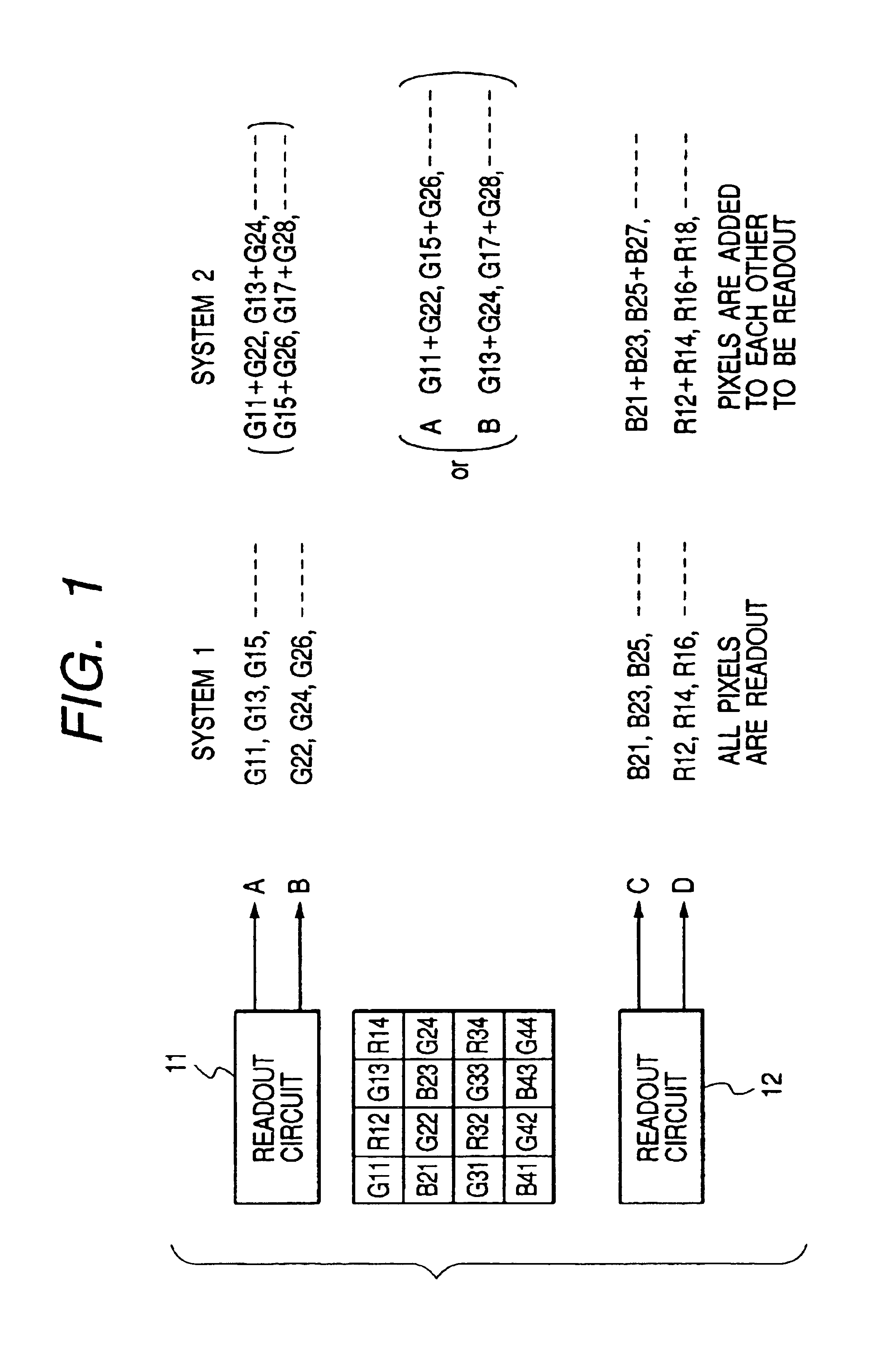
[0098]FIG. 1 is a schematic diagram for explaining a pixel signal reading method employed by a color image pickup apparatus according to the first embodiment of the present invention. In FIG. 1, four channels are provided for the output of an image pickup device, and color filters of individual pixels that are arranged as a matrix form in the image pickup device, are arranged in a checkerboard: G (green) filters are arranged in half of the checkerboard pattern, and R (red) filters and B (blue) filters are each arranged in the other half of the remaining.

[0099]For high definition reading (system 1), each pixel signal is read individually. That is, pixel signals G11, G13, G15, . . . are output by a reading circuit 11 via output channel A; pixel signals G22, G24, G26, . . . are output by the reading circuit 11 via output channel B; pixel signals B21, B23, B25, . . . are output by a reading circuit 12 via output channel C; and pixel signals...

second embodiment

[0125]A second embodiment according to the present invention will now be described.

[0126]FIG. 7 is a schematic diagram for explaining a pixel signal reading method employed in a color image pickup apparatus according to the second embodiment of the present invention. In FIG. 7, four channels (four outputs) are provided for an image pickup device, and color filters for individual pixels that are arranged in a matrix form in the image pickup device, are arranged in a checkerboard: G (green) filters are arranged in half of the checkerboard pattern, and R (red) filters and B (blue) filters are each arranged in the other half of the checkerboard.

[0127]For high definition reading (system 1), all the pixel signals are read individually. That is, pixel signals G11, G13, G15, . . . are output by a reading circuit 111 via output channel A; pixel signals G22, G24, G26, . . . are output by the reading circuit 111 via output channel B; pixel signals B21, B23, B25, . . . are output by the reading...

third embodiment

[0156]A third embodiment according to the present invention will now be described.

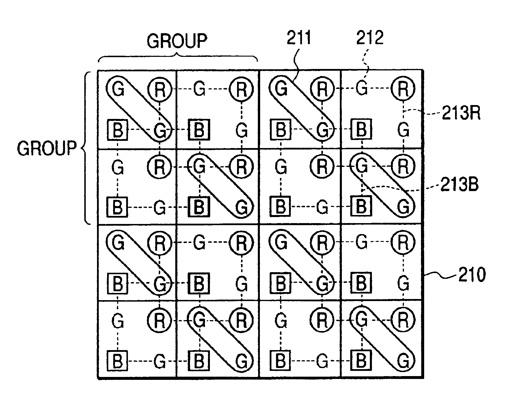
[0157]FIGS. 14A and 14B are conceptual diagrams for an addition method according to this embodiment. In FIG. 14A, a general bayer arrangement 100 is the filter arrangement in which G is positioned, in a checkerboard, between R and B. The addition method of this embodiment will be explained by referring to FIG. 14A. In this example, a 2×2 pixel block, wherein G is positioned, in a checkerboard, between R and B, is regarded as one element that has a basic color structure, and four adjacent elements constitute one group. As for G, two pixcels adjacent to each other in an oblique direction in the element are added together. A block 211 denotes the G pixels to be added together. As for R and B, basically, only R and B pixels in the element are selected, and in this example, four pixels of the same color in the four adjacent elements (four pixels of the same color in one group) are added together. As a resul...


PUM


Abstract

An image pickup apparatus comprises a plurality of pixels arranged in a matrix form, first color filters arranged in an oblique direction for the pixels, second and third color filters arranged so that a same color is arranged in a horizontal direction, a circuit for adding together signals of two or more pixels each having the first color filter, which are adjacent to each other in an oblique direction, and a circuit for adding together the signals of two or more pixels each having the second color filter, which are arranged in a horizontal direction, and for adding together the signals of two or more pixels each having the third color filter, which are arranged in the horizontal direction.

Description

BACKGROUND OF THE INVENTION[0001]1. Field of the Invention[0002]The present invention relates to an image pickup apparatus and to an image pickup system that employs the apparatus, and for example, relates to a color image pickup apparatus, which can select an operation for reading individual original pixel signals and an operation for adding the signals together and reading the result, and to an image pickup system that uses the apparatus.[0003]2. Related Background Art[0004]Nowadays, digital still cameras are available that are equipped with pickup devices that have two million pixels. The availability of pickup devices having such a high resolution is the result of the effort devoted to matching the image quality available with silver halide photographic equipment. These new cameras are especially used for static images. Conventional NTSC video cameras have only around four hundred thousand pixels, and reading speeds of about 13.5 MHz for interlaced scanning and 27 MHz for progre...

Claims


Application Information

Patent Timeline
IPC IPC(8): H04N5/335H04N5/347H04N5/374H04N9/07
CPCH04N9/045H04N3/1562H04N25/46H04N25/70H04N25/778H04N23/84H04N25/136H04N25/76H04N25/134H04N25/75
Inventor HASHIMOTO, SEIJISHINOHARA, MAHITOKOCHI, TETSUNOBUHAYASHI, HIDETOSHI
Owner CANON KK
Learn More