Method and apparatus for self-calibration of a tunable-source phase shifting interferometer

a self-calibration and interferometer technology, applied in the field of interferometers, can solve the problems of generality of known prior art system residual offset errors of the tunable-source sour

Active Publication Date: 2006-01-31
MITUTOYO CORP
View PDF15 Cites 18 Cited by
  • Summary
  • Abstract
  • Description
  • Claims
  • Application Information

AI Technical Summary

Benefits of technology

[0009]In contrast, the present invention provides systems and methods for providing signals indicative of, or usable to determine, the offset contribution to various detector channel signals in an interferometer by varying the source wavelength while acquiring the offset indicating signals. In contrast to prior art methods, the present invention provides a method that can be implemented for each or any optical path of an interferometer, without the need for additional special optical paths or controllable path length variations. Furthermore, systems and methods according to the present invention do not require any moving parts to adjust or control optical path lengths. However, for interferometer systems that already include such components, the systems and methods according to the present invention can still be used in place of or in addition to the other methods of offset correction methods available for such systems, to eliminate or compensate additional residual sources of offset error that cannot be eliminated by the other methods available for such systems.
[0020]In accordance with a further aspect of the invention, in one embodiment the interferometer comprises at least one two-dimensional camera and each respective set of at least first and second respective detector channels has detectors that comprise pixels of the at least one two-dimensional camera, and a set of interpolated interferometer measurements corresponding to respective nominal locations on the test object are usable to provide a two-dimensional surface height profile of at least a portion of the test object, the two-dimensional surface height profile being relatively free of offset-induced errors.

Problems solved by technology

That is, these errors, in view of the signals provided by the multiple phase-shifting image generating structure disclosed in the '330 patent, equally affect multiple measurement signals provided in that system.
Furthermore, residual sources of offset error generally remain in known prior art systems.

Method used


Image

  • Method and apparatus for self-calibration of a tunable-source phase shifting interferometer
  • Method and apparatus for self-calibration of a tunable-source phase shifting interferometer
  • Method and apparatus for self-calibration of a tunable-source phase shifting interferometer

Examples


Embodiment Construction

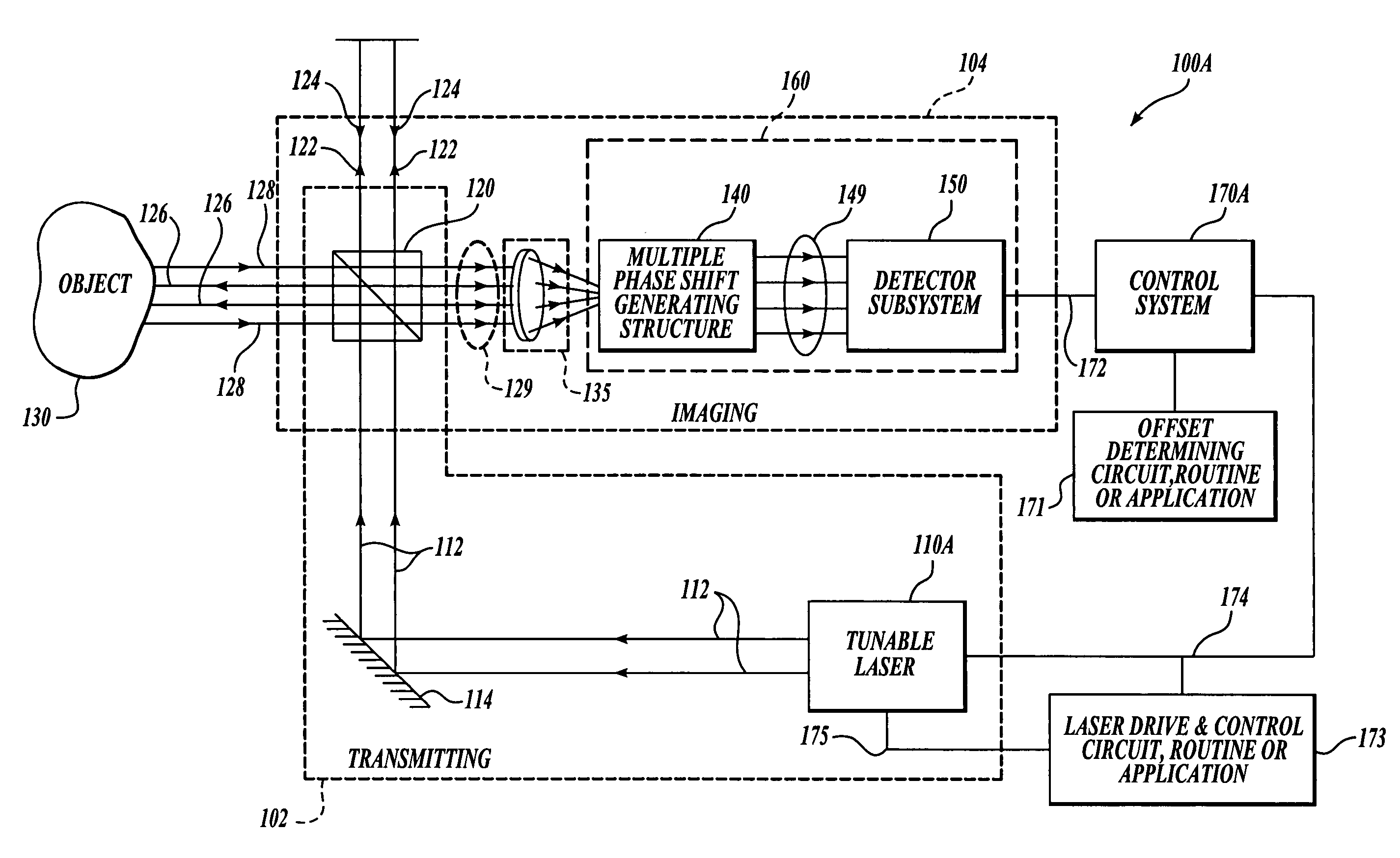
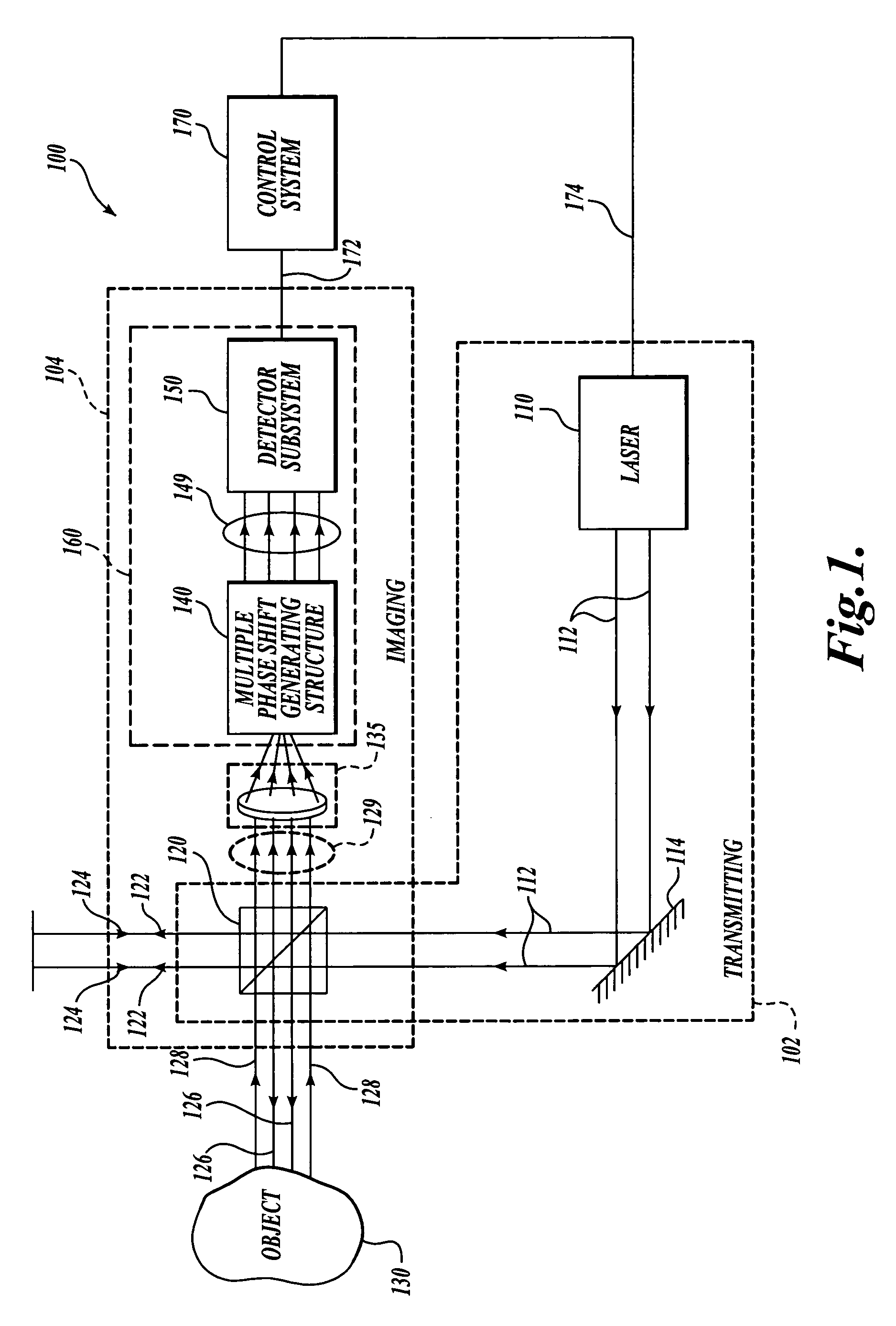
[0036]FIG. 1 shows a first generic embodiment of an interferometer system 100, which is usable with various exemplary embodiments of the present invention. As shown in FIG. 1, the interferometer system 100 generally includes a transmitting portion 102 and an imaging portion 104. The transmitting portion 102 includes a laser source 110 that transmits a coherent light wavefront 112. As will be described in more detail below, in various exemplary embodiments according to the present invention the laser source 110 is tunable or otherwise able to provide a varying radiation frequency and illumination wavelength. In various exemplary embodiments, the laser source 110 may include wavelength modulation, or any other now known or later-developed device, structure or apparatus that can provide a varying wavelength of light over time, for the coherent light wavefront 112. As used herein, the term “light” encompasses not only visible light, but also any part of the electromagnetic spectrum that...


PUM


Abstract

A conventional phase shifting interferometer that is used for measuring distances (e.g., in the micron range) typically provides two orthogonal, or quadrature, signals. The output signals typically include an offset that introduces a related measurement error unless it is compensated or eliminated. A standard way for eliminating offsets is to generate and / or process additional signals that are phase shifted by 180 degrees, or other known amounts. In contrast, the present invention provides a signal indicative of the offset contribution to a detector signal in an interferometer by varying the wavelength of radiation from the illumination source of the interferometer during the time that the offset determining signal is acquired or integrated by that detector. The method can be conveniently implemented with each signal detection channel of an interferometer, for a variety of interferometer designs. The method determines the offset error within a very short time period and without the need to provide additional or adjusted optical paths, or controlled phase shifts.

Description

FIELD OF THE INVENTION[0001]This invention relates generally to interferometers, and more particularly to a method and apparatus for self-calibration of a tunable-source phase shifting interferometer.BACKGROUND OF THE INVENTION[0002]A number of phase shifting interferometer designs (as well as other types of interferometer designs used for measuring distances) are intended to provide 2 quadrature signals, ideally orthogonal output signals V1 ideal and V2 ideal as shown by EQUATIONS 1 and 2 below: V1⁢ideal=Sin⁢2⁢⁢πλ⁢z(Eq.⁢1)V2⁢ideal=Cos⁢2⁢⁢πλ⁢z(Eq.⁢2)where λ is the wavelength of radiation used in the interferometer and z is the optical pathlength difference (OPD) between the interfering test object path light beam and reference path light beam. These two quadrature input signals of an interferometer should ideally both arise from light coming from precisely the same portion of the test object. The OPD z for that portion of the test object can then be determined to high resolution wit...

Claims


Application Information

Patent Timeline
Patent Type & Authority Patents(United States)
IPC IPC(8): G01B9/02
CPCG01B9/02004G01B9/02081G01B2290/70
Inventor NAHUM, MICHAEL
Owner MITUTOYO CORP
Why Eureka
Try Eureka