Intelligent access control system

a control system and intelligent technology, applied in the field oftelephonic communications, can solve problems such as data loss, communication interruption, and difficulty in ensuring the integrity of the access control system, and achieve the effects of ensuring the integrity of the access control system

Inactive Publication Date: 2006-01-31
VERIZON PATENT & LICENSING INC
View PDF24 Cites 44 Cited by
  • Summary
  • Abstract
  • Description
  • Claims
  • Application Information

AI Technical Summary

Benefits of technology

[0017]According to a still further embodiment, the local loop generation equipment is a doorbell answering system, and the central office is adapted to implement advanced intelligent network (AIN) features. These AIN capabilities permit a premises occupant to receive doorbell answering system telephone calls while already engaged in another telephone call. These AIN capabilities may also be employed to provide a premises occupant with a cancel door bell call waiting feature such that call waiting tones will not be sent to the premises telephone when a visitor activates the doorbell answering system and a call is already in progress. Finally, these AIN capabilities may be used to provide a premises occupant with a call waiting feature such that only calls from the doorbell answering system will cause call waiting tones to be sent to the premises telephone.

Problems solved by technology

However, this communication is subject to interruption at any time.
However, the open circuit is also problematic in cases where the transfer of data is interrupted.
The subscriber loses data during this interruption, and may also be faced with the inconvenience of having to re-log into an online service.
Although the foregoing example deals with local loop generation equipment in the form of a doorbell answering system, other types of local loop generation equipment present similar problems.
If, for example, the resident is communicating over the Internet, the Internet connection will typically be lost.
These breaks in communication may occur unexpectedly, unpredictably, and repeatedly, causing the resident to become frustrated with the overall quality of telephone service.

Method used


Image

  • Intelligent access control system
  • Intelligent access control system
  • Intelligent access control system

Examples


Embodiment Construction

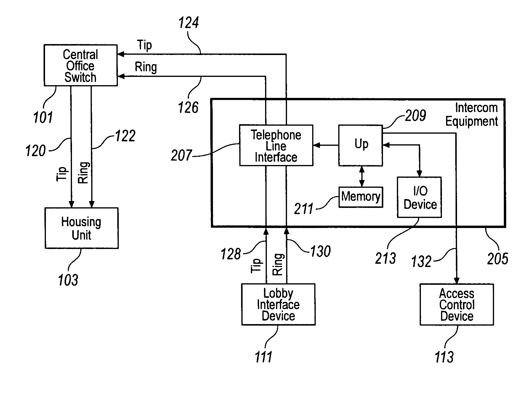
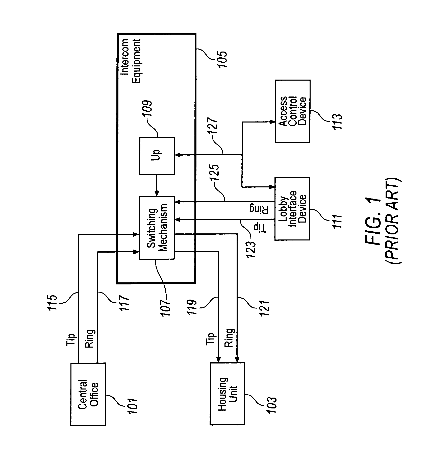
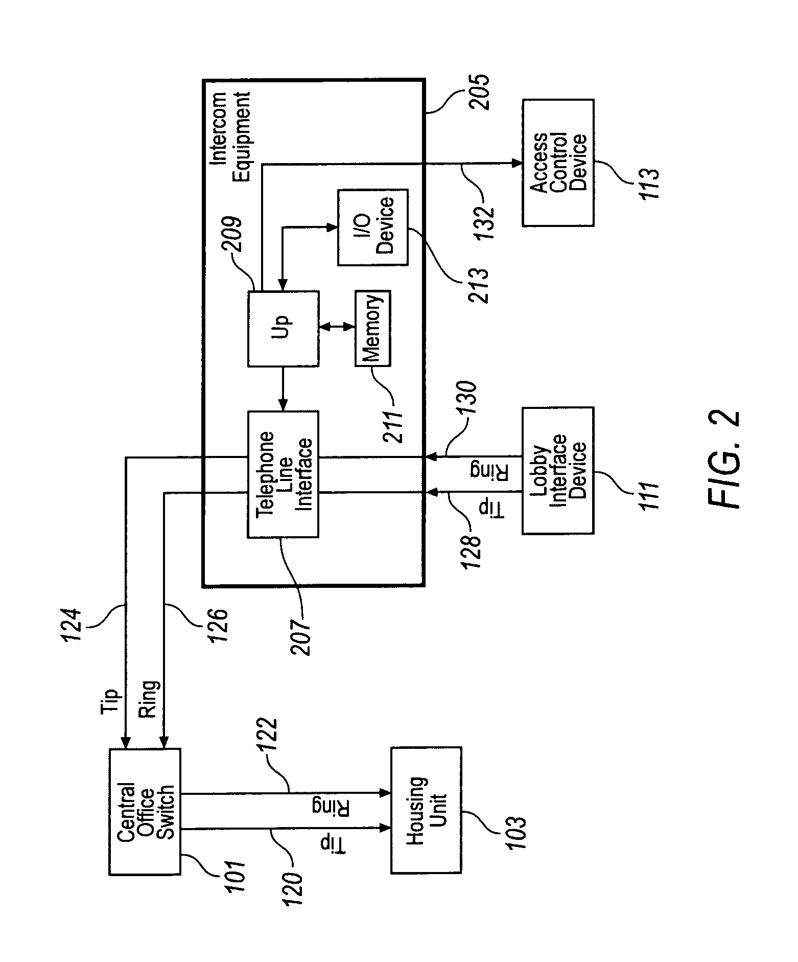
[0026]Refer to FIG. 2 which is an electrical block diagram of a system equipped to provide minimal interruption of communications between a central office and a customer in an operational environment where local loop generation equipment is used. One fundamental distinction between the system of FIG. 2 and the prior art configuration of FIG. 1 is that the system of FIG. 2 does not place intercom equipment 205 in series between central office 101 and housing unit 103. Considering FIG. 2 in greater detail, note that only one housing unit 103 is shown. This is for purposes of illustration only as, in a more typical application, intercom equipment 105 would provide service to a plurality of housing units 103 served by central office 101. Such housing units 103 may, but need not, represent individual apartments, townhouses, condominiums, offices, and / or single family homes which are organized into a larger complex, subdivision, campus, and / or planned unit development. As shown, tip / ring ...


PUM


Abstract

In operational environments where local loop generation equipment is used, communication interruptions between a central office and a customer premises device is minimized by using a dedicated communications link between the local loop generation equipment and the central office. A processing mechanism at the central office determines if, when, and under what circumstances the customer premises device will be notified in response to the activation of local loop generation equipment. This eliminates the need to place local loop generation equipment in series with a communications path that runs between the central office and the customer premises. The central office may provide the dedicated communications link in the form of a telephone line which is equipped to place outgoing local calls, but not equipped to receive incoming calls, and not equipped to place long-distance calls.

Description

FIELD OF THE INVENTION[0001]The present invention relates generally to telephonic communications, and, more particularly, to techniques for overcoming shortcomings of local loop generation equipment.BACKGROUND OF THE INVENTION[0002]Ever-increasing numbers of telephone customers may be coupled to local loop generation equipment, examples of which are security systems, doorbell answering devices, and access control mechanisms. In particular, doorbell answering systems are commonly utilized in multi-family housing units. These systems generally place a switching mechanism in series with the tip / ring lines running from the telephone company central switching office to the customer premises. Normally, this switching mechanism is closed, completing a circuit between the switching office and the customer premises. In this closed state, customers are able to communicate voice and / or data over their telephone lines as if the access control system was not even present. However, this communica...

Claims


Application Information

Patent Timeline
Patent Type & Authority Patents(United States)
IPC IPC(8): H04M3/42
CPCH04M11/025
Inventor ALLEN, JOSEPHJONES, DOUGLAS R.O'CALLAGHAN, DANIEL J.
Owner VERIZON PATENT & LICENSING INC
Why Eureka
Try Eureka