Fluid level sensor

a technology of fluid level sensor and sensor body, which is applied in the direction of liquid/fluent solid measurement, instruments, machines/engines, etc., can solve the problems of reducing the size and cost of the sensor, unable to perform both transmission and reception functions for both reference and measurement signals using a single transceiver, and improving the design and operation. , the effect of simple and economical manufactur

Active Publication Date: 2006-02-07
TI GRP AUTOMOTIVE SYST LLC
View PDF16 Cites 40 Cited by
  • Summary
  • Abstract
  • Description
  • Claims
  • Application Information

AI Technical Summary

Benefits of technology

[0012]Objects, features and advantages of this invention include providing a fluid level sensor for use in a fluid container that has an improved design and operation, particularly in vehicle fuel tanks experiencing low fuel levels or sig

Problems solved by technology

However, the velocity of ultrasonic signals in fluids may be affected by a number of variables, including the composition and temperature of the fluid.
However, a fluid level sensor constructed according to the Däges et al. patent is unable to perform both transmission and reception functions for both reference and measurement signals usin

Method used


Image

  • Fluid level sensor
  • Fluid level sensor
  • Fluid level sensor

Examples


Embodiment Construction

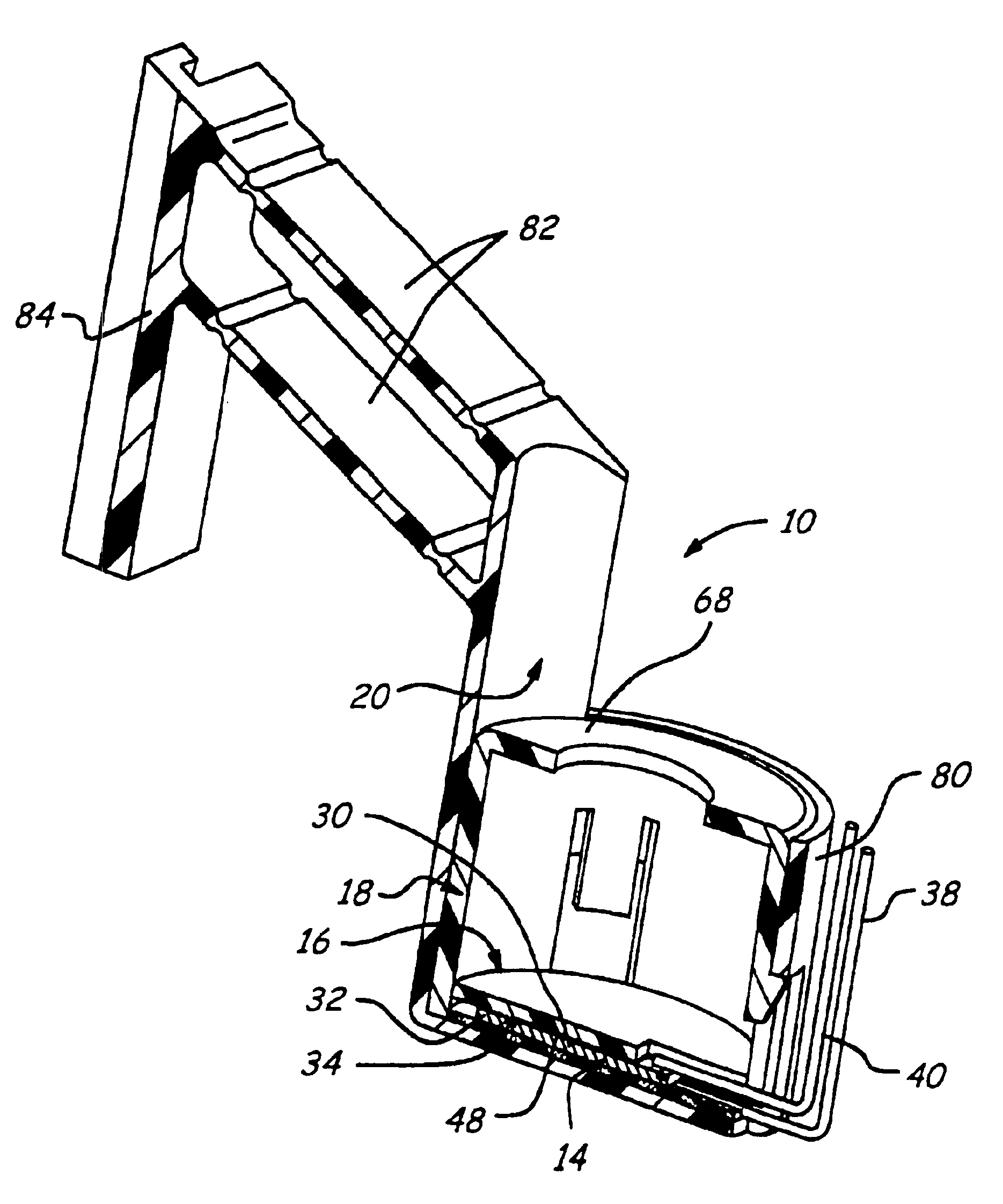
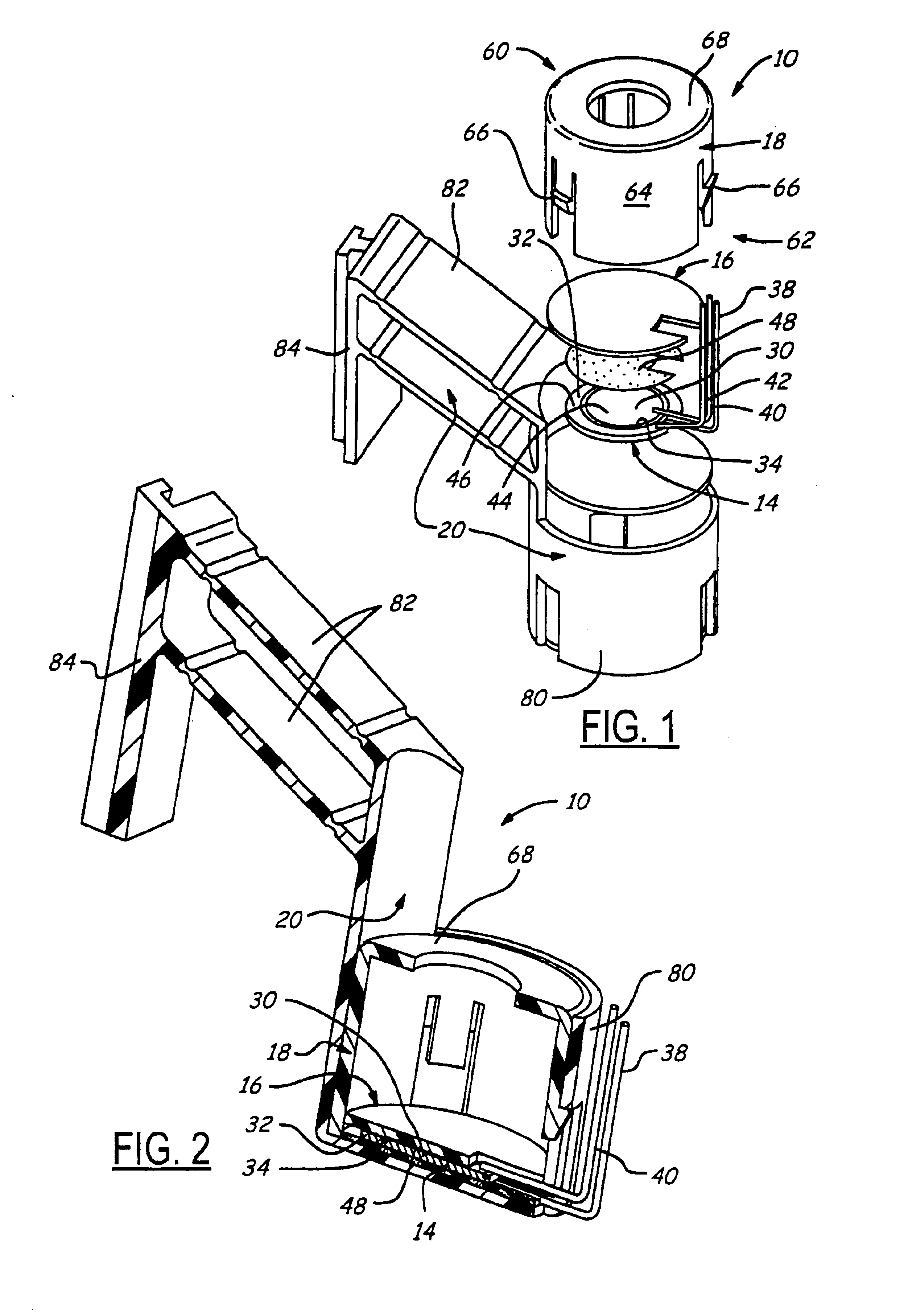
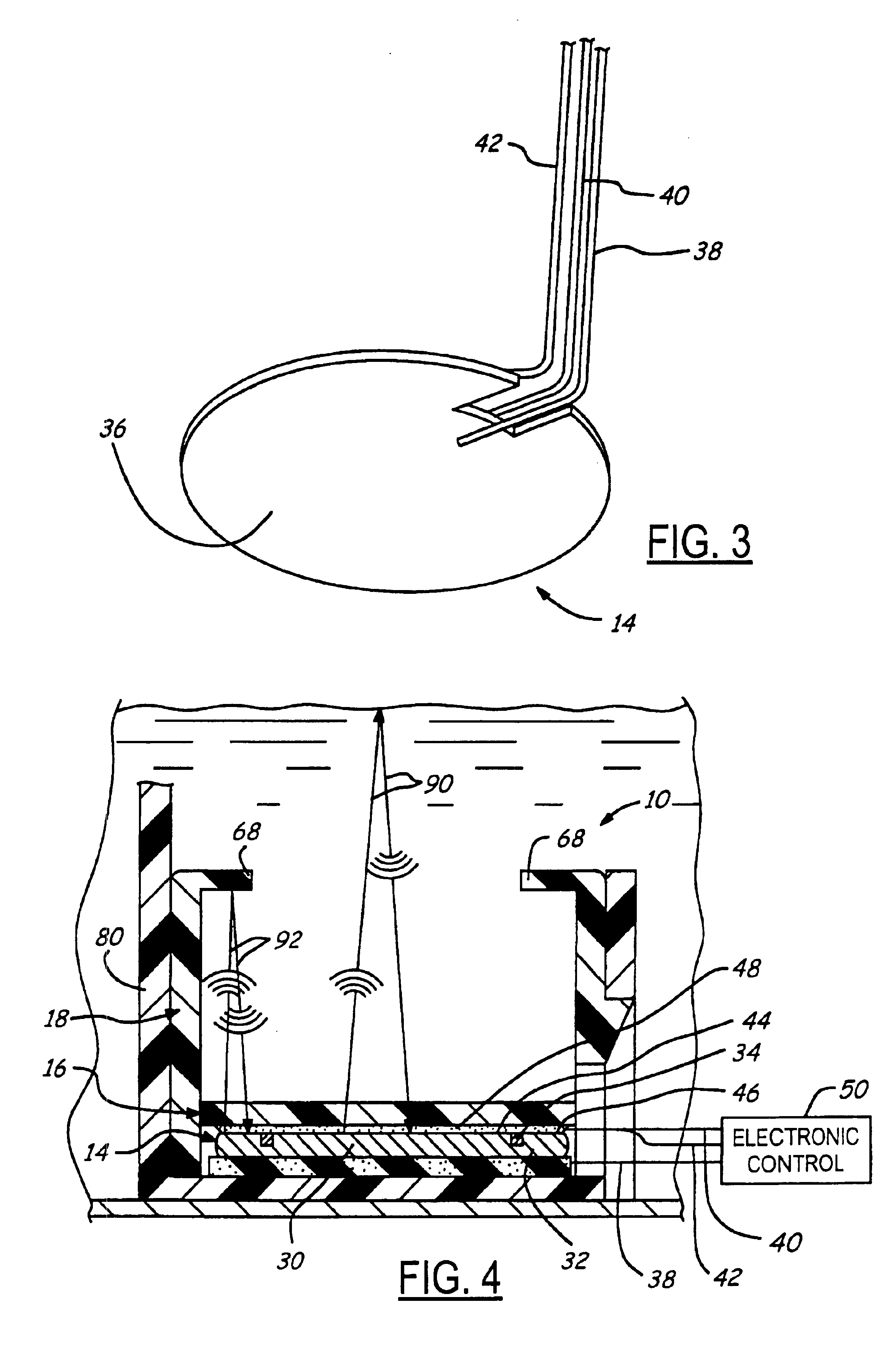
[0019]With reference to FIGS. 1 and 2, there are shown two different views of a first embodiment of the fluid level sensor 10 of the present invention. Typically, fluid level sensor 10 is located towards the bottom of a fluid container, preferably a vehicle fuel tank, and includes a transceiver that emits ultrasonic signals upwardly into the surrounding fluid. Some of the emitted signals, referred to as measurement signals, reflect off of the fluid surface and travels back to the transceiver, such that the roundtrip echo time of the signals may be used to measure the fluid level. In order to further increase the accuracy of the sensor, some of the emitted ultrasonic signals, referred to as reference signals, are purposely directed towards and reflect off of a reference element, which is positioned a known distance from the transceiver. Because the distance and roundtrip echo time of the reference signals are known, a precise signal velocity value may be calculated. This velocity val...


PUM


Abstract

An ultrasonic fluid level sensor for use in a fluid container, preferably a vehicle fuel tank. The fluid level sensor generally includes a single transceiver having measurement and reference sections, an impedance layer and a housing having a reference element and an aperture. The measurement and reference sections are independent ultrasonic transceivers that are disk-shaped and ring-shaped, respectively, and are generally concentric. The reference element is a ring-shaped portion of the housing that is axially spaced from the reference section at a known distance, and the aperture is a disk-shaped opening in the housing that is axially spaced from the measurement section. In operation, the sensor is able to provide signals to an electronic controller that enable the controller to determine a signal velocity calibrated measurement of the fluid level that is compensated for temperature, fluid composition, and other velocity affecting factors.

Description

REFERENCE TO RELATED APPLICATION[0001]Applicant claims the benefit of U.S. Provisional Application No. 60 / 395,519, filed Jul. 12, 2002.TECHNICAL FIELD[0002]The present invention generally relates to fluid level sensors, and more particularly, to fluid level sensors for use in vehicle fuel tanks.BACKGROUND OF THE INVENTION[0003]It is known to mount a fluid level sensor in the bottom of a fluid container for purposes of measuring the fluid level. Sensors of this type often include an ultrasonic transceiver that transmits ultrasonic pulses from the bottom of the container upwards through the fluid to the fluid surface. At the fluid surface, a portion of the ultrasonic pulses are downwardly reflected back to the transceiver. The transceiver receives the reflected pulses and in response, sends a corresponding signal to an electronic controller. The controller is able to calculate the depth of the fluid by knowing the roundtrip echo time of the ultrasonic signal and the approximate veloci...

Claims


Application Information

Patent Timeline
IPC IPC(8): G01F23/00G01F23/28F02M37/00G01D18/00G01F23/296
CPCG01F23/2968G01F23/2962
Inventor FORGUE, JOHN R.
Owner TI GRP AUTOMOTIVE SYST LLC
Why Eureka
Try Eureka