Gas sensor and method of detecting gas concentration

a gas sensor and gas concentration technology, applied in the field of gas sensors, can solve problems such as errors in prior-art hydrocarbon gas sensors

Inactive Publication Date: 2006-02-07
DENSO CORP +1
View PDF11 Cites 8 Cited by
  • Summary
  • Abstract
  • Description
  • Claims
  • Application Information

AI Technical Summary

Benefits of technology

[0007]It is a first object of this invention to provide a gas sensor for detecting a specific-component concentration in a gas which is accurate even when measurement environments vary.
[0008]It is a second object of this invention to provide a method of detecting a specific-component concentration in a gas which is accurate even when measurement environments vary.

Problems solved by technology

As will be explained later, a prior-art hydrocarbon gas sensor tends to have an error in the result of detection of a hydrocarbon gas concentration in the case where measurement environments vary.

Method used


Image

  • Gas sensor and method of detecting gas concentration
  • Gas sensor and method of detecting gas concentration
  • Gas sensor and method of detecting gas concentration

Examples


first specific embodiment

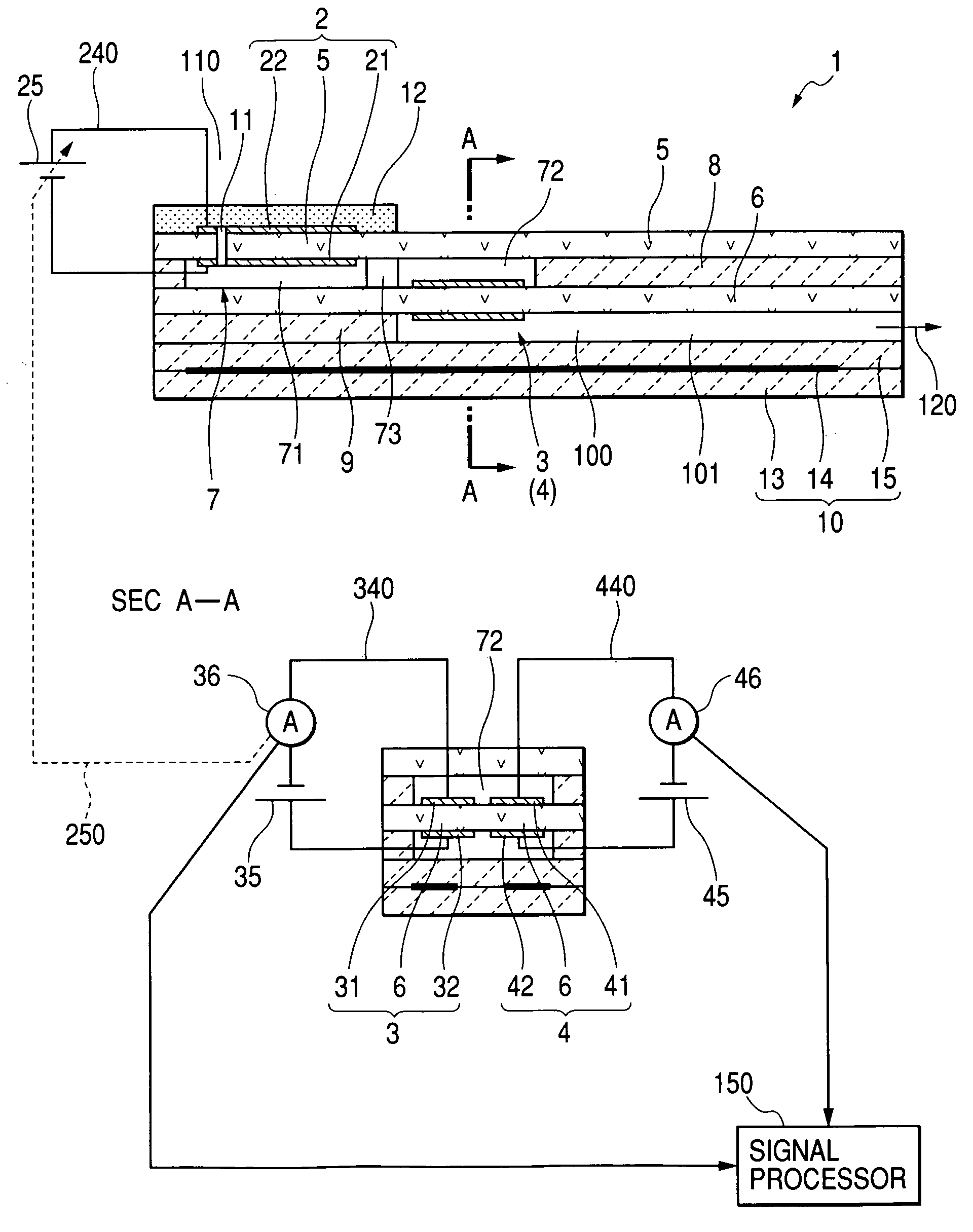
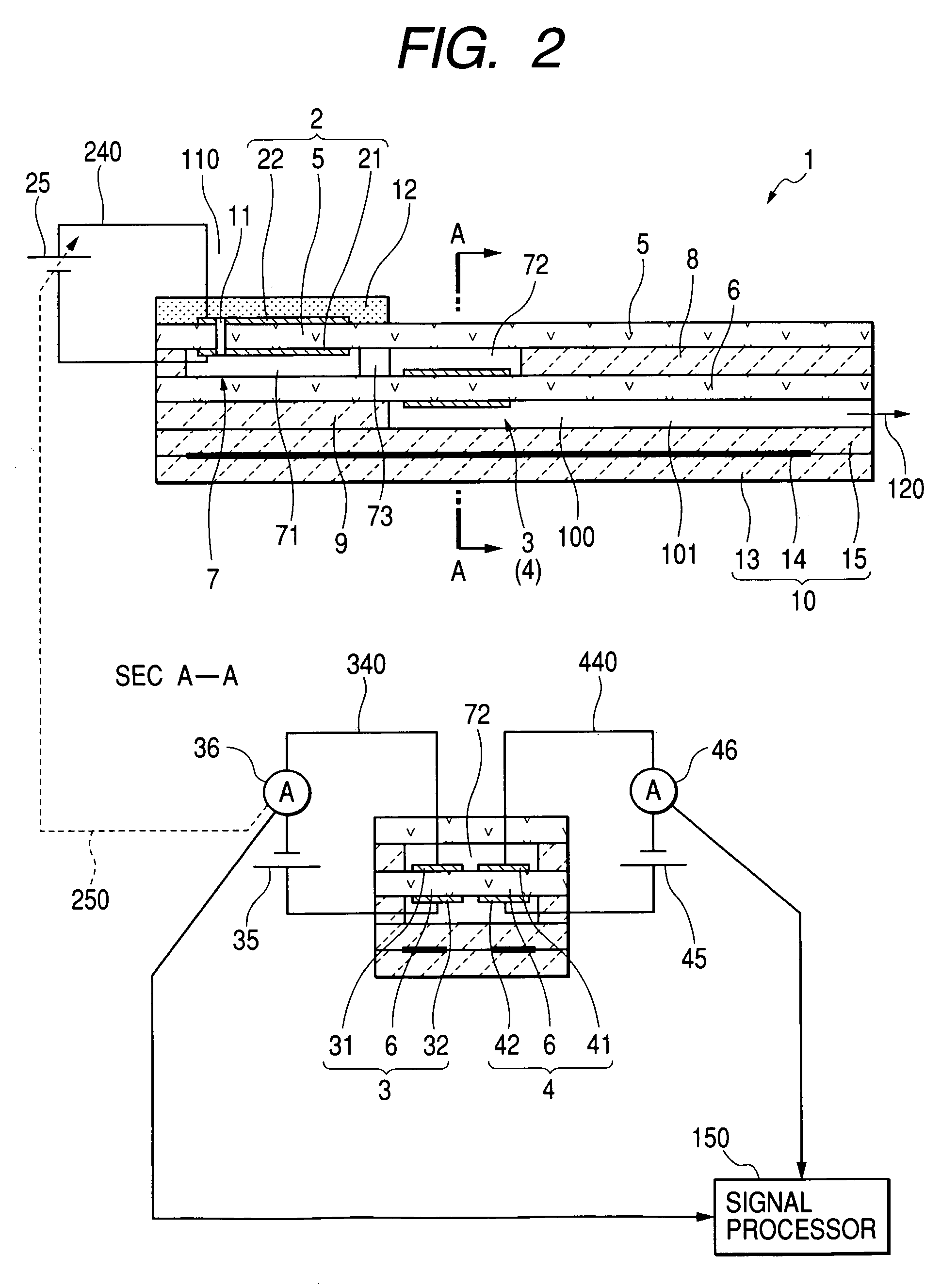
[0083]FIG. 2 shows a gas sensor 1 according to a first specific embodiment of this invention. The gas sensor 1 is designed to measure the concentration of hydrocarbon (HC) in a measurement gas such as an exhaust gas produced by an automotive engine. The detected HC concentration can be utilized in controlling the burning of an air-fuel mixture in the automotive engine.

[0084]As shown in FIG. 2, the gas sensor 1 includes a measurement gas chamber 7 into which a measurement gas (an exhaust gas) is introduced. The gas sensor 1 further includes an oxygen pumping cell 2, an oxygen monitor cell 3, and a sensor cell 4.

[0085]The oxygen pumping cell 2 has a solid electrolyte member 5 and a pair of electrodes 21 and 22. The electrodes 21 and 22 are provided on the lower and upper surfaces of the solid electrolyte member 5, respectively. The electrodes 21 and 22 are opposed to each other. The electrode 21 is exposed in the measurement gas chamber 7. The electrode 22 extends on an outer surface ...

second specific embodiment

[0137]A gas sensor 1 of a second specific embodiment of this invention is similar to that of the first specific embodiment thereof except for a design change mentioned hereafter.

[0138]In the gas sensor 1 of the second specific embodiment of this invention, the measurement-gas-side electrode 31 of the oxygen monitor cell 3 is active to hydrocarbon including methane (CH4). Specifically, the measurement-gas-side electrode 31 has a sufficient oxidizing activity with respect to hydrocarbon including methane (CH4). The hydrocarbon oxidizing activity of the measurement-gas-side electrode 41 in the sensor cell 4 is lower than that of the measurement-gas-side electrode 31 in the oxygen monitor cell 3.

[0139]Specifically, the measurement-gas-side electrode 31 in the oxygen monitor cell 3 includes a porous cermet electrode containing Pt (platinum). The electrode 31 is highly active to hydrocarbon including methane (CH4). In other words, the electrode 31 has a high oxidizing activity with respec...

third specific embodiment

[0144]FIG. 9 shows a gas sensor 1A according to a third specific embodiment of this invention. The gas sensor 1A is similar to the gas sensor 1 (FIG. 2) except for design changes mentioned hereafter.

[0145]As shown in FIG. 9, the gas sensor 1A includes a measurement gas chamber 7 into which a measurement gas (an exhaust gas) is introduced. The measurement gas chamber 7 is divided into a first measurement gas chamber 71 and a second measurement gas chamber 72 which communicate with each other. The gas sensor 1A further includes an oxygen pumping cell 2, an oxygen monitor cell 3, and a sensor cell 4.

[0146]The oxygen pumping cell 2 has a solid electrolyte member 6 and a pair of electrodes 21 and 22. The electrodes 21 and 22 are provided on the upper and lower surfaces of the solid electrolyte member 6, respectively. The electrode 21 is exposed in the first measurement gas chamber 71. The electrode 22 is exposed in a reference gas chamber 100 into which an atmosphere is introduced as a r...


PUM

PropertyMeasurementUnit
voltageaaaaaaaaaa
diffusion resistanceaaaaaaaaaa
concentrationaaaaaaaaaa

Abstract

A gas sensor includes a measurement gas chamber into which a measurement gas is introduced. An oxygen pumping cell adjusts an oxygen concentration in the measurement gas chamber. An oxygen monitor cell has a monitor electrode exposed in the measurement gas chamber. The monitor electrode has an oxidizing activity with respect to a specific component of the measurement gas. A sensor cell has a sensor electrode exposed in the measurement gas chamber. The sensor electrode has an oxidizing activity with respect to the specific component of the measurement gas which is lower than the oxidizing activity of the monitor electrode. An oxygen-ion current in the oxygen monitor cell is detected. An oxygen-ion current in the sensor cell is detected. A concentration of the specific component of the measurement gas is detected from a relation between the detected oxygen-ion currents in the oxygen monitor cell and the sensor cell.

Description

BACKGROUND OF THE INVENTION[0001]1. Field of the Invention[0002]This invention relates to a gas sensor for detecting a specific-component concentration in a gas. In addition, this invention relates to a method of detecting a specific-component concentration in a gas.[0003]2. Description of the Related Art[0004]European patent application publication number 0678740 A1 corresponding to Japanese patent application publication number 8-271476 discloses a sensing device for measuring a concentration of a gas component of a measurement gas. The sensing device in European application 0678740 A1 includes a first internal space into which the measurement gas is introduced from an external measurement-gas space via a first diffusion controlling passage. A flow of the measurement gas toward the first internal space receives a predetermined diffusion resistance provided by the first diffusion controlling passage. The first internal space communicates with a second internal space via a second di...

Claims


Application Information

Patent Timeline
Patent Type & Authority Patents(United States)
IPC IPC(8): G01N27/407G01N27/416G01N27/419
CPCG01N27/419
Inventor MIZUTANI, KEIGOSUZUKI, KAZUNORISAITO, TOSHITAKAMAKINO, DAISUKE
Owner DENSO CORP
Why Eureka
Try Eureka