[0013]There are many advantages of the materials used in the present invention over the prior art. A principal
advantage of the present invention is that all materials have a very close
thermal expansion match in that they all possess a very low linear expansion. Furthermore, all materials have limited chemical expansion and this is particularly important for the
perovskite chosen for the electronic phase of the dense layer. In this regard, the use of such perovskite is particularly advantageous as opposed to a
metal in that a
noble metal would have to be used to prevent oxidation. The obvious problem with the use of a
noble metal is one of expense. At the same time, the vanadium containing perovskite is a particularly difficult material to sinter. However, as will be discussed below, the inventors herein have solved such problem allowing its use in the
oxygen transport membrane. Furthermore, the support is particularly robust due to the use of partially stabilized zirconia.
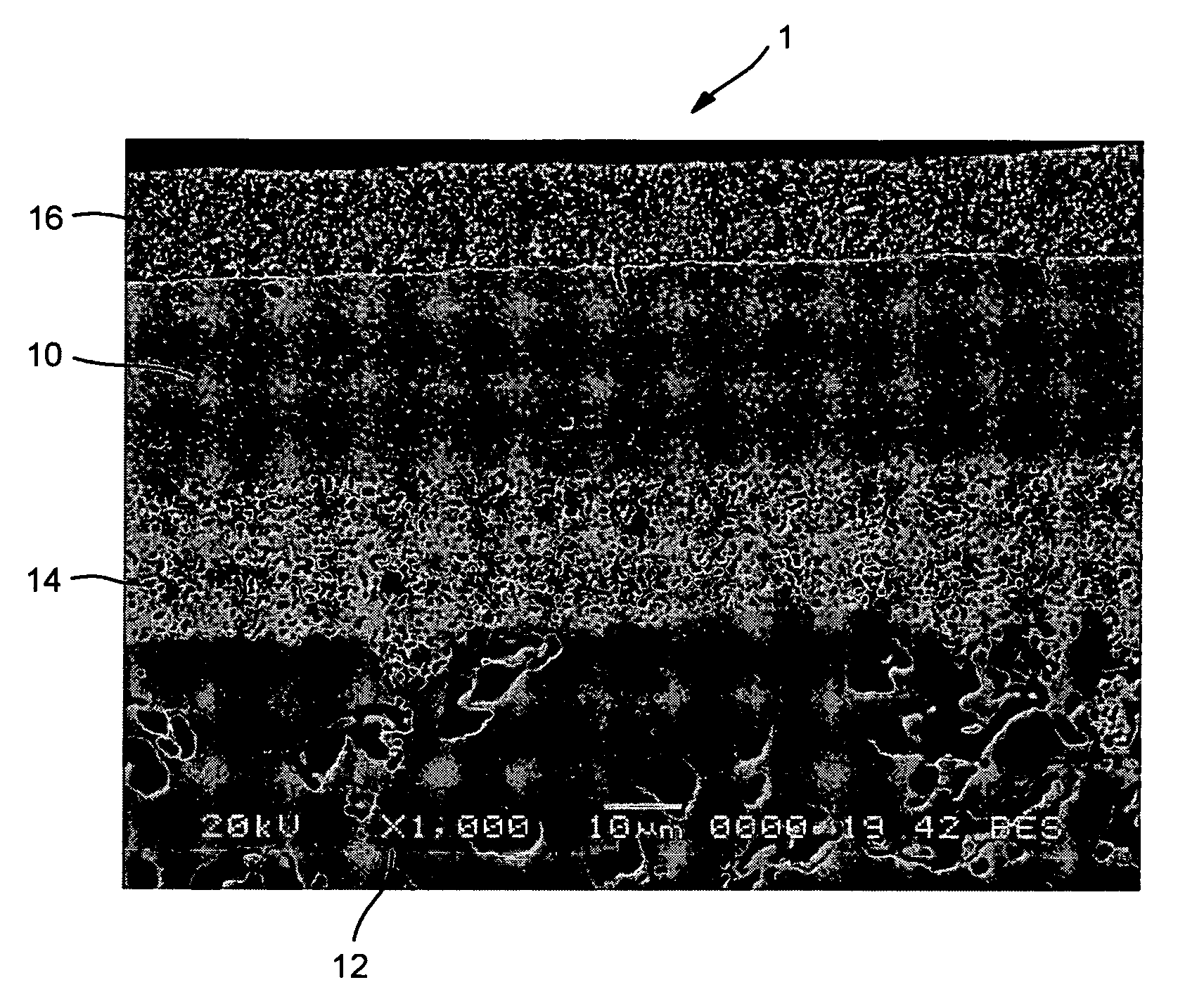
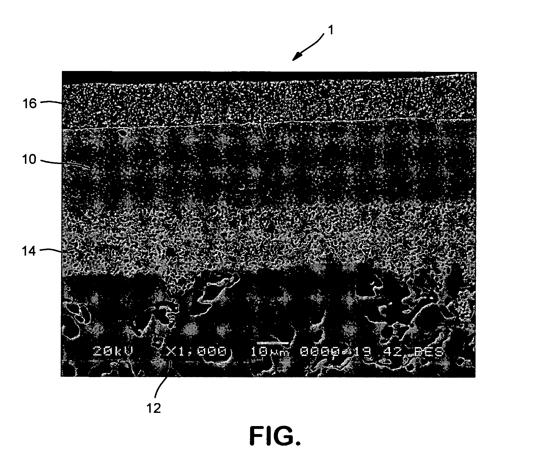
[0014]A porous intermediate layer can be provided between the dense layer and the porous support layer. Such porous intermediate layer can be composed of the electronic phase and the ionic phase of the dense layer. Furthermore, a surface exchange layer, overlying the dense layer can be provided so that the dense layer is located between the surface exchange layer and the porous intermediate layer. The surface exchange layer can incorporate a further electronic conductor composed of (Lax′″Sr1−x′″)y′″MO3−δ, where x′″ is from about 0.2 to about 0.8, y′″ is from about 0.95 to 1, M=Mn, Fe and a further ionic conductor composed of ZrxivScyivAzivO2−δ, where yiv is from about 0.08 to about 0.15, ziv is from about 0.01 to about 0.03, xiv+yiv+ziv=1 and A=Y, Ce.
[0015]Preferably, the ionic phase constitutes between about 35 percent and 65 percent by volume of each of the dense layer and the intermediate
porous layer, remainder the electronic phase and the further ionic conductor constitutes between about 35 percent and about 65 percent by volume of the surface exchange layer, remainder the further electronic conductor. Preferably, the ionic phase constitutes about 50 percent by volume of each of the dense layer and the intermediate porous layer, remainder the electronic phase and the further ionic conductor constitutes between about 50 percent by volume of the surface exchange layer, remainder the electronic conductor.
[0016]Preferably, in the dense layer, the electronic phase is (La0.825Sr0.175)0.97Cr0.76Mn0.225V0.015O3−δ and the ionic phase is Zr0.89Sc0.1Y0.01O2−δ. The porous support layer is preferably formed of Zr0.97Y0.03O2−δ. In the surface exchange layer, if used, the further ionic conductor is Zr0.89Sc0.1Y0.01O2−δ and the further electronic conductor is La0.8Sr0.2FeO3−δ. In a particularly preferred embodiment of the present invention, the porous intermediate layer has a first thickness of between about 20 micron and about 60 micron, a first average pore size of between about 0.1 micron and about 0.5 micron and a first
porosity of between about 40 percent and about 60 percent. In such embodiment, the porous support layer can preferably have a second thickness of between about 1 mm and about 2.5 mm, a second average pore size of between about 2 micron and about 5 micron and a second
porosity of between about 40 percent and about 60 percent. The overlying porous support layer can have a third thickness of between about 10 micron and about 25 micron, a third average pore size of between about 0.1 micron and about 0.5 micron and a third
porosity of between about 40 percent and about 60 percent.
[0017]It is to be noted, that as used herein and in the claims, the term “pore size” means average
pore diameter as determined by quantitative stereological line intersection analysis, a technique well known in the art.

