Micro-electromechanical system inertial sensor

Inactive Publication Date: 2010-01-05
NANCHANG O FILM OPTICAL ELECTRONICS TECH CO LTD
View PDF18 Cites 62 Cited by
  • Summary
  • Abstract
  • Description
  • Claims
  • Application Information

AI Technical Summary

Benefits of technology

[0011]In accordance with the present invention, a MEMS gyroscope is provided in which the same spring is commonly shared by both resonant motions of the resonator, but in which the spring extends in opposite directions. This arrangement results in the mech

Problems solved by technology

However, due to the small sensing area available for capacitive sensing, MEMS gyroscopes that use ring structures typically exhibit high angle random walk, or rotation-rate white noise.
This breaks the symmetry of the structure and adversely affects the drift performance of MEMS gyroscopes that use ring structures.
However, these devices are not substantially planar in configuration, and consequently, are more difficult to manufacture and package.
As a practical matter, the symmetry of a symme

Method used


Image

  • Micro-electromechanical system inertial sensor
  • Micro-electromechanical system inertial sensor
  • Micro-electromechanical system inertial sensor

Examples


Embodiment Construction

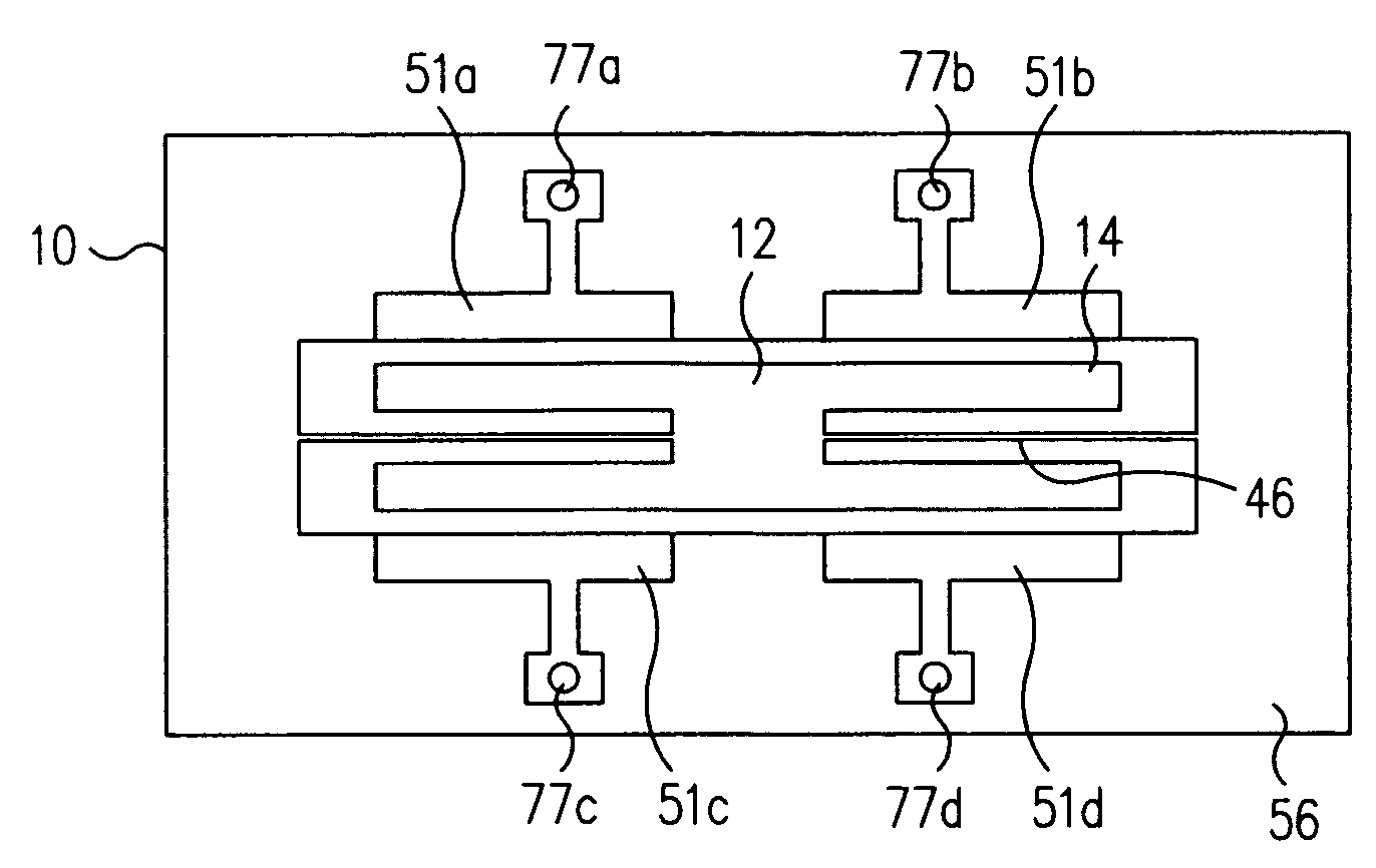
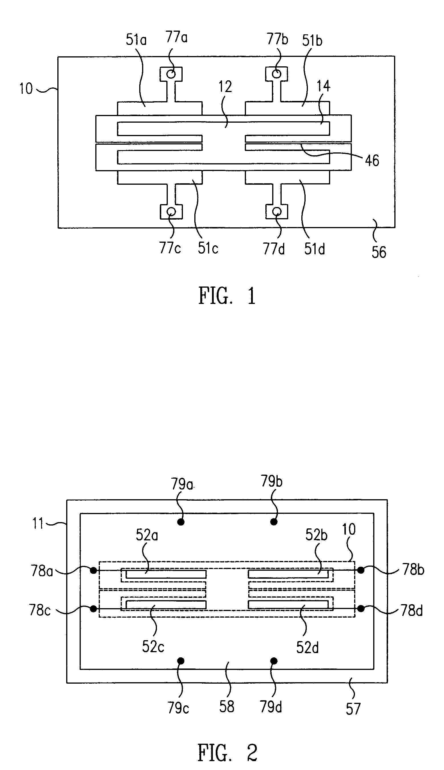
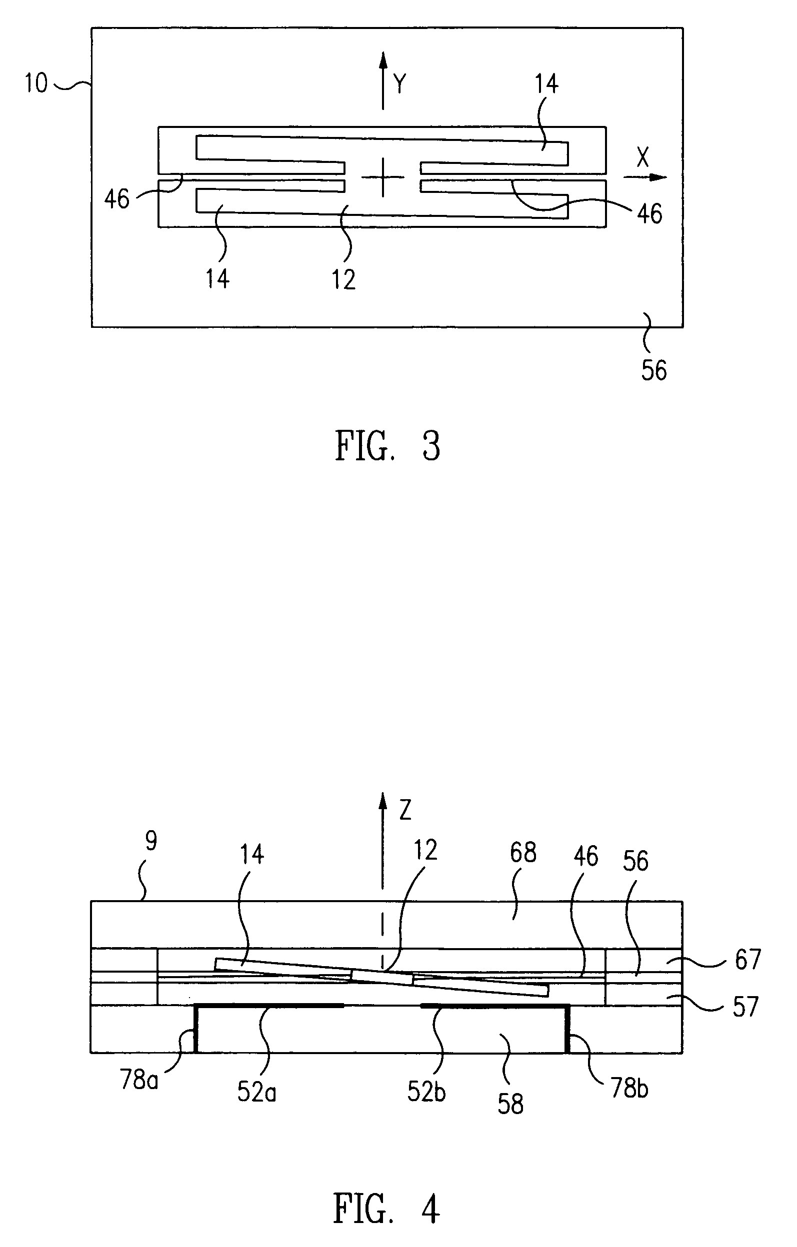
[0035]An exemplary embodiment of a MEMS inertial sensor 9 in accordance with the present invention includes two major portions: A resonator portion 10, comprising a movable, symmetrical planar mass 12, and a fixed baseplate portion 11. As illustrated in FIG. 3, the movable mass 12, sometimes referred to as a “proof mass,” is flexibly suspended from a planar support frame 56 by one or more opposed “flexures,” or springs 46, and the resonator and support frame, in turn, are sandwiched between generally planar lower and upper cover portions 58 and 68, respectively, of the baseplate portion 11 by a pair of spacer rings or frames 57 and 67, respectively, as illustrated in the cross-sectional elevation view of the sensor of FIG. 4.

[0036]FIGS. 1 and 3 are top plan views of the resonator portion 10 of an inertial sensor 9 according to a first exemplary embodiment of the present invention. In this particular embodiment, a substantially planar, H-shaped mass 12 is flexibly coupled to the supp...


PUM


Abstract

A micro-machined MEMS resonator gyroscope and accelerometer is fabricated from an epilayer semiconductor wafer to incorporate a substantially planar, H-shaped resonator mass suspended from a support plate by two opposed elongated springs that couple to the relatively short crossbar member of the H. The masses are harmonically oscillated relative to the support plate and a baseplate portion, and two orthogonal modes of the structure corresponding to the two nearly degenerate fundamental torsional modes thereof are used for sensing angular rate about one axis, and linear acceleration along two axes, of the sensor. The H-shaped mass advantageously incorporates a relatively high length-to-width aspect ratio, and in one embodiment, the springs may advantageously incorporate either a square cross-section, such that the structure can be tuned to substantially match the fundamental frequencies of the two resonance modes of the structure by removing, e.g., by an etching process, a small amount of material from the upper surfaces of the springs.

Description

CROSS-REFERENCE TO RELATED APPLICATIONS[0001]This application claims benefit of U.S. Provisional Application No. 60 / 574,677, filed May 26, 2004.BACKGROUND OF THE INVENTION[0002]1. Field of the Invention[0003]This invention relates to micro-electromechanical system (“MEMS”) devices that sense inertial rotation and acceleration, commonly referred to as gyroscopes and accelerometers. More specifically, the invention relates to MEMS resonant gyroscopes and accelerometers.[0004]2. Related Art[0005]Precision micro-electromechanical accelerometers and gyroscopes have wide application in the field of inertial navigation and guidance. Such sensors are manufactured using sophisticated semiconductor manufacturing, or “micromachining,” techniques, and typically incorporate at least one planar mass, typically of silicon, pendulously mounted adjacent to at least one planar structure, also typically of silicon, so as to define an electrical capacitance between the mass and structure. Movement of t...

Claims


Application Information

Patent Timeline
IPC IPC(8): G01P9/04
CPCG01C19/5719G01P15/097G01P15/125G01P15/14G01P15/18
Inventor GUTIERREZ, ROMAN C.TANG, TONY K.
Owner NANCHANG O FILM OPTICAL ELECTRONICS TECH CO LTD
Why Eureka
Try Eureka