Biobased microbattery

a micro-batteries and bio-based technology, applied in the field of micro-batteries and methods for making same, can solve the problems of low discharge rate, toxicity, flammability, explosion,

Inactive Publication Date: 2006-02-07
THE UNITED STATES OF AMERICA AS REPRESENTED BY THE SECRETARY OF THE NAVY
View PDF1 Cites 39 Cited by
  • Summary
  • Abstract
  • Description
  • Claims
  • Application Information

AI Technical Summary

Problems solved by technology

Unfortunately, batteries suffer from one or more of the following traits: toxicity, flammability, explosivity, low energy density, low discharge rate, instability, expensive material use, high fabrication costs, short cycle life, production complexity, and excessive design precautions.

Method used


Image

  • Biobased microbattery
  • Biobased microbattery
  • Biobased microbattery

Examples


example 1a

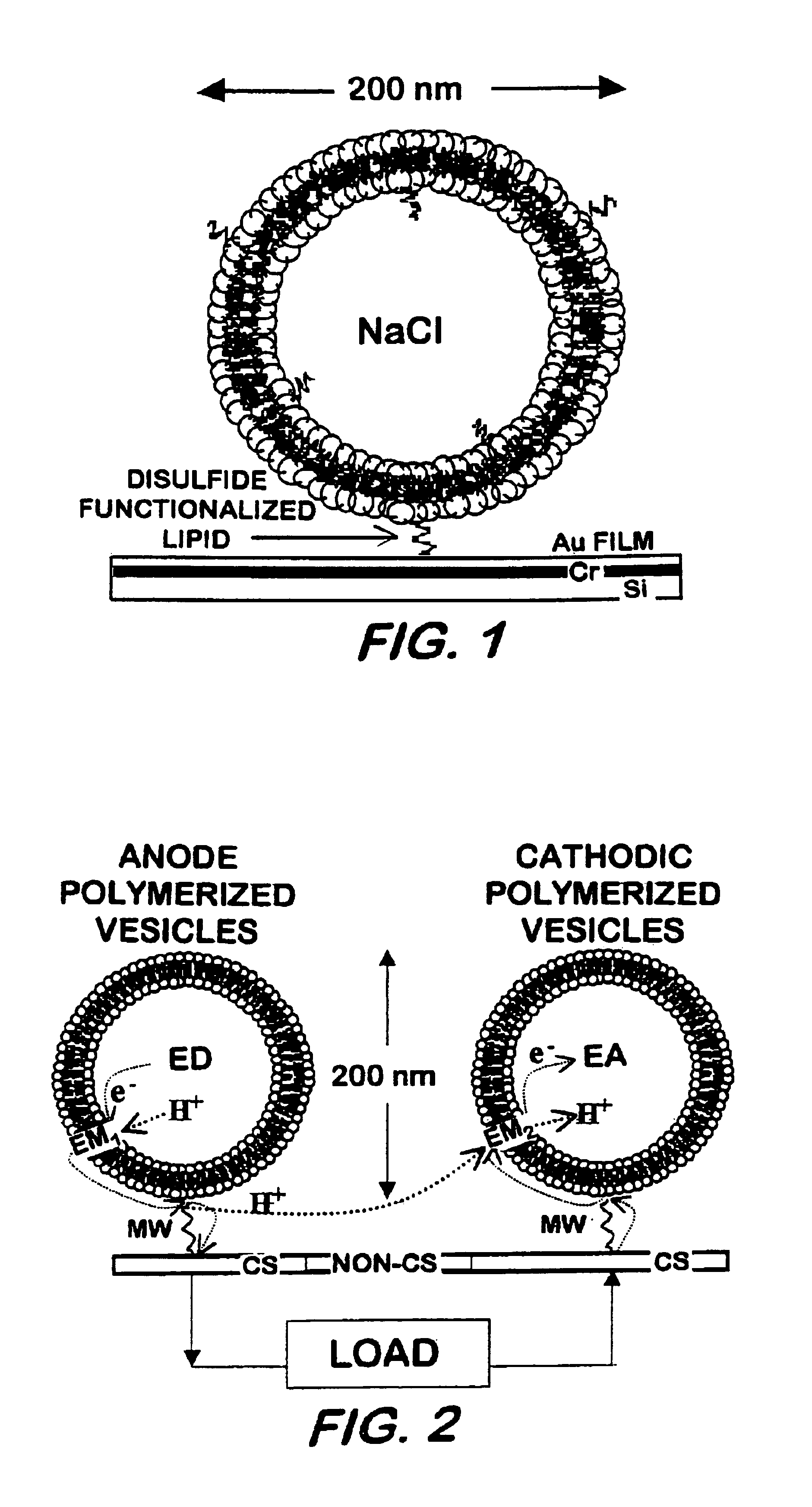
[0033]Vesicle formation—25 mg of DC8,9PC was placed in a scintillation vial and dispersed with 5 mL of deionized water. The sample was vortexed for 1 minute, heated to 50° C. for 2 hours, and subsequently extruded 10 times through 0.2 μm Nucleopore membranes using a Lipex extruder (Lipex Biomembranes Inc., Vancouver BC). The sample was UV-irradiated for 10 minutes at 8° C. using a Rayonett Photochemical reactor (So. New England Ultraviolet Co., Hamden, Conn.). Polymerized vesicle average size (˜200 nm), shape (spherical), and lamellarity (uni-) were determined by dynamic laser light scattering using a Coulter Model N4MD (Coulter Electronic, In., Miami, Fla.) and / or by a Zeiss transmission electron microscopy (TEM) or by an 8100 Hitachi high resolution TEM.

example 1b

[0034]Vesicle formation—25 mg of 1-palmitoyl-2-(tricosa-10,12-diynoyl)-sn-glycero-3-phosphocholine PC8,9PC was placed in a scintillation vial and dispersed with 5 mL of deionized water. The sample was vortexed for 1 minute, heated to 50° C. for 2 hours, and subsequently extruded 10 times through 0.2 μm Nucleopore membranes. The sample was UV-irradiated for 10 minutes at 8° C. Polymerized vesicle average size (˜200 nm), shape (spherical), and lamellarity (uni-) were determined by dynamic laser light scattering and / or by TEM.

example 1c

[0035]Vesicle formation—25 mg of DC10PC was placed in a scintillation vial and dispersed with 5 mL of deuterated water. The sample was vortexed for 1 minute, heated to 50° C. for 2 hours, and subsequently extruded 10 times through 0.2 μm Nucleopore membranes. The sample was exposed to 10 megaradians of γ-radiation using a 60Co source. Polymerized vesicle average size (˜130 nm), shape (spherical), and lamellarity (uni-) were determined by dynamic laser light scattering and / or by TEM.


PUM

PropertyMeasurementUnit
thicknessaaaaaaaaaa
diameteraaaaaaaaaa
thicknessaaaaaaaaaa

Abstract

A galvanic cell having a cathode, an anode, and an electrolyte. The cathode and anode each have vesicles, an electroactive species encapsulated into the vesicles, a conducting substrate, and functionalized tethers immobilizing the vesicles to the substrates. The electrolyte is in contact with both conducting substrates. At least some of the vesicles contain benzoquinone and/or hydroquinone.

Description

[0001]This application is a continuation-in-part application of pending U.S. patent application Ser. No. 09 / 939,288, filed on Aug. 24, 2001 now U.S. Pat. No. 6,689,142, incorporated herein by reference.BACKGROUND OF THE INVENTION[0002]1. Field of the Invention[0003]The present invention relates generally to microbatteries and methods for making same, more specifically to bio-based microbatteries and methods for making same.[0004]2. Description of the Prior Art[0005]Currently, numerous types of battery designs have been commercialized, resulting from application-based niches dependent on size, power, energy, convenience, and marketability. Unfortunately, batteries suffer from one or more of the following traits: toxicity, flammability, explosivity, low energy density, low discharge rate, instability, expensive material use, high fabrication costs, short cycle life, production complexity, and excessive design precautions. The major concerns are eliminating toxic components and fabrica...

Claims


Application Information

Patent Timeline
Patent Type & Authority Patents(United States)
IPC IPC(8): H01M4/60B05D5/12H01M2/16H01M2/18H01M4/02H01M4/36H01M4/50H01M4/52H01M4/66H01M10/36
CPCH01M4/02H01M4/36H01M4/52H01M10/36H01M4/66H01M4/60H01M4/50H01M4/661H01M4/663H01M4/664Y02E60/10
Inventor STANISH, IVANSINGH, ALOK
Owner THE UNITED STATES OF AMERICA AS REPRESENTED BY THE SECRETARY OF THE NAVY
Why Eureka
Try Eureka