Control system for a sputtering system

a control system and sputtering technology, applied in the direction of electric generator control, dynamo-electric converter control, vacuum evaporation coating, etc., can solve the problems of warning or error signals, fewer or zero atoms of target material being freed from the target, and subsequent termination of the sputtering process

Active Publication Date: 2006-02-07
MKS INSTR INC
View PDF68 Cites 31 Cited by
  • Summary
  • Abstract
  • Description
  • Claims
  • Application Information

AI Technical Summary

Problems solved by technology

Sputtering system faults (such as, warning or error signals) may occur during operation.
These faults are indicative of problems in the sputtering process or the onset of problems that may have adverse effects on the sputtering process.
One such fault occurs when the power generator of a sputtering system outputs a voltage that is below a specified threshold; this condition can result in fewer or zero atoms of target material being freed from the target.
Further, another such fault occurs when the power generator outputs a current density to the plasma chamber above a specified threshold value; this condition can result in arcing and subsequent termination of the sputtering process due to the presence of the arcing.
Multiple faults, however, may occur within a short period of time during the operation of the sputtering system.
A control system's reaction to each of the individual faults may not be optimum where there are multiple faults.

Method used


Image

  • Control system for a sputtering system
  • Control system for a sputtering system
  • Control system for a sputtering system

Examples


Embodiment Construction

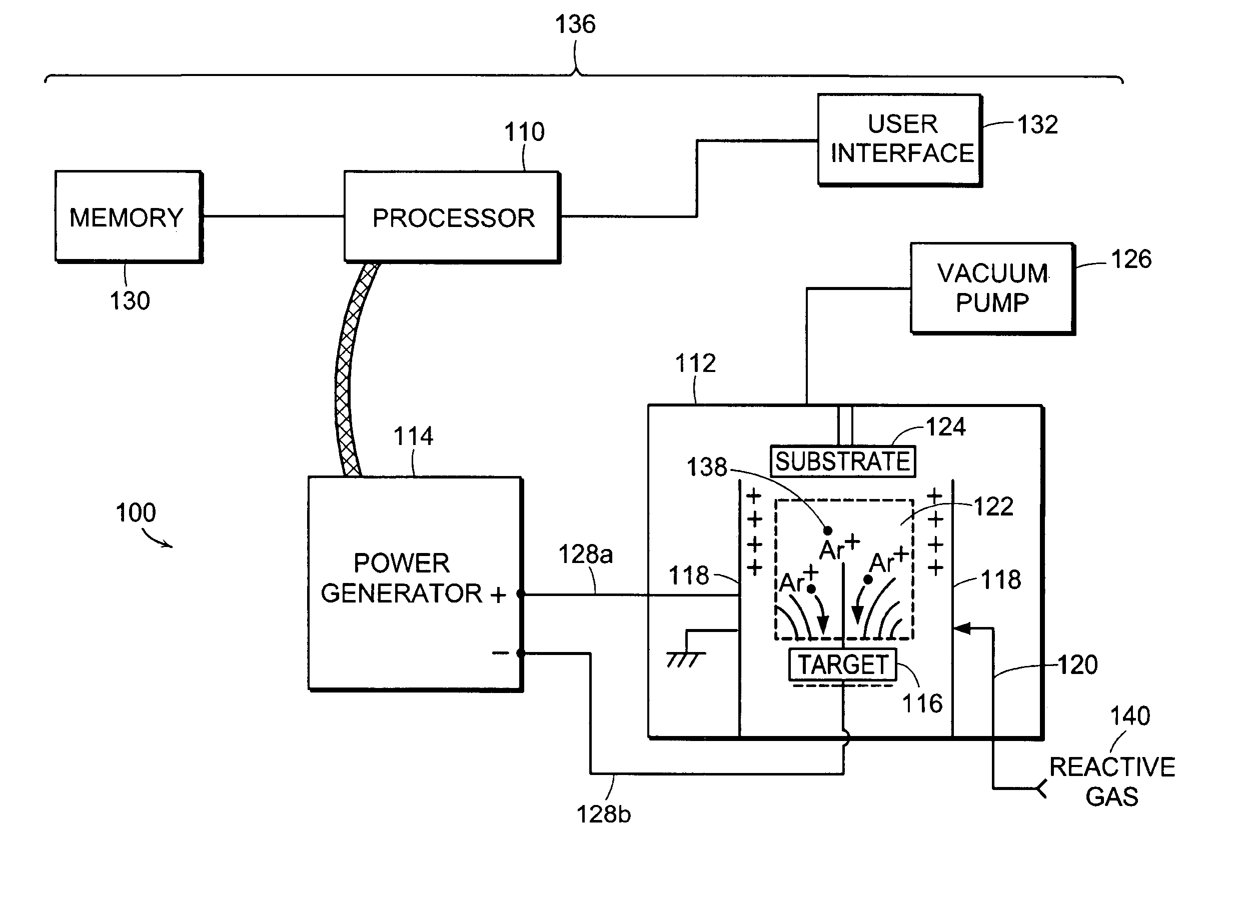
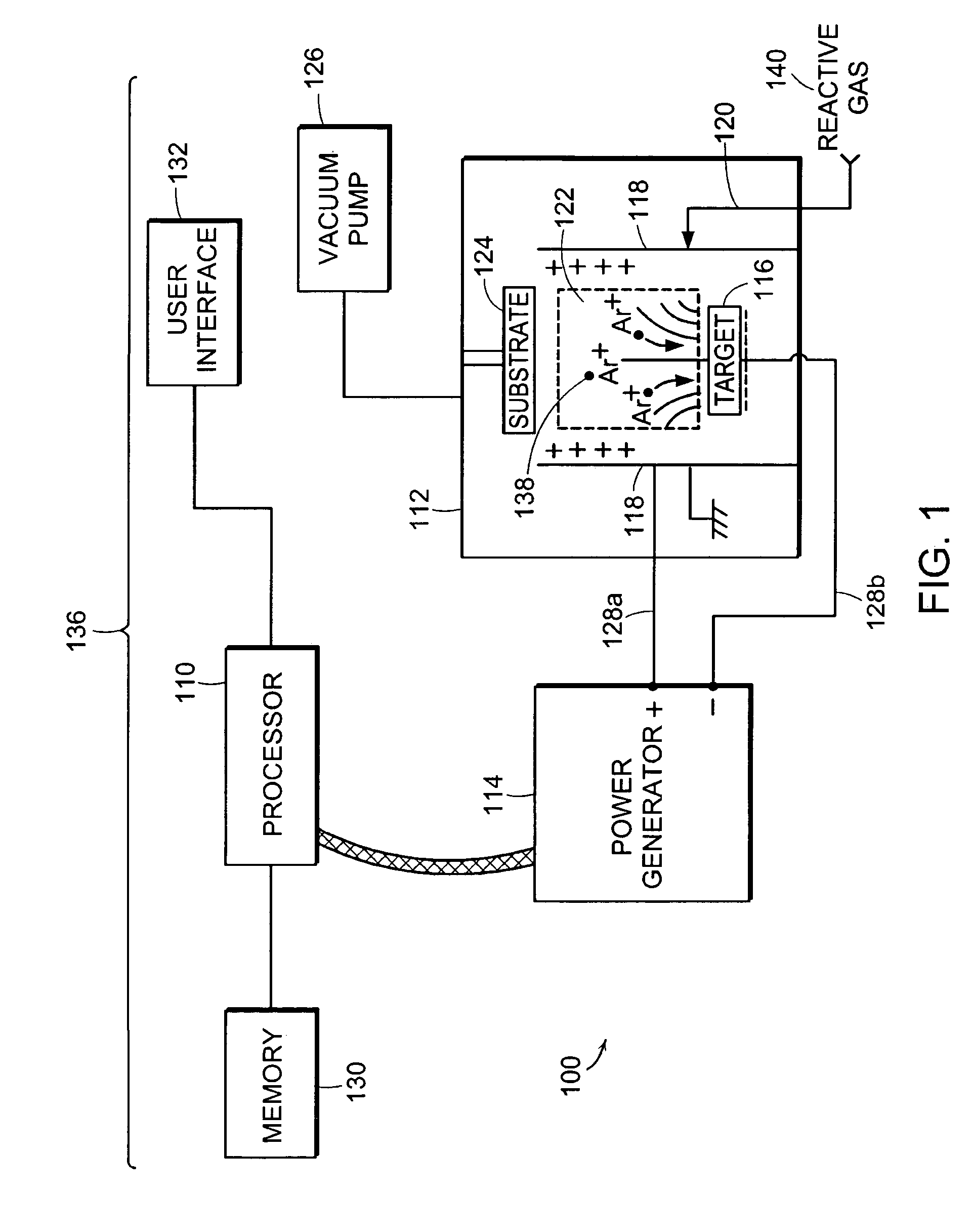
[0023]FIG. 1 illustrates one embodiment of a fault handling system 136 used to control a sputtering system 100 according to the invention. The sputtering system 100 includes a plasma chamber 112 and a power generator 114. The fault handling system includes a processor 110 that is in signal communication with a memory 130 and a user interface 132. The processor 110 generates one or more command signals based upon a fault handling algorithm and a plurality of fault status signals to affect the operation of the power generator 114. It is helpful to understand the operation of the sputtering system 100 to more fully describe the associated fault handling system 136.

[0024]During a typical operation of the sputtering system 100, the pressure in the plasma chamber 112 is adjusted by a vacuum pump 126 while a controlled amount of a noble gas, for example, argon gas is introduced. Positively charged argon ions 138 (Ar+) are accelerated during operation by a field towards a target 116 (also r...


PUM

PropertyMeasurementUnit
frequencyaaaaaaaaaa
voltageaaaaaaaaaa
voltageaaaaaaaaaa

Abstract

A fault handling algorithm processes a plurality of fault status signals from a sputtering system in a period of time to generate at least one command signal for affecting the operation of a power generator.

Description

FIELD OF THE INVENTION[0001]The invention generally relates to fault handling systems in the field of plasma sputtering. In particular, the invention relates to a fault handling system and methods for controlling operation of a power generator used in a sputtering system.BACKGROUND OF THE INVENTION[0002]Plasma sputtering processes are extensively used in the semiconductor, flat panel, data storage, hard coating and industrial glass coating industries. In a sputtering process atoms of a material are liberated from a target material and deposited onto a substrate. In a reactive sputtering process, alternatively, atoms of a material are liberated from a target material allowing the atoms to react with a gas to form a coating that is, subsequently, deposited onto a substrate. In the semiconductor industry a reactive sputtering process may be employed, for example, to deposit a dielectric insulating layer (such as, silicon nitride) onto a silicon wafer. In the hard coating industry, a re...

Claims


Application Information

Patent Timeline
Patent Type & Authority Patents(United States)
IPC IPC(8): H02P9/10H02P11/00H02P9/00H02P9/04H02P9/44C23C14/54H01J37/32H01J37/34H01L21/00
CPCH01J37/32082H01J37/34H01L21/67253H01L21/67069C23C14/54C23C14/34
Inventor TRACY, MARK D.KLEIN, JESSE N.
Owner MKS INSTR INC
Why Eureka
Try Eureka