Micro-power stand-by mode

a technology of standby mode and micro-power, which is applied in emergency power supply arrangements, color televisions, television systems, etc., can solve problems such as reducing the operation efficiency of electronic devices, and achieve the effect of minimizing utilization

Inactive Publication Date: 2006-02-07
SATURN LICENSING LLC
View PDF17 Cites 35 Cited by
  • Summary
  • Abstract
  • Description
  • Claims
  • Application Information

AI Technical Summary

Benefits of technology

[0009]In one embodiment, a method for operating in micro-power stand-by mode includes connecting the AC line to the main power supply circuit via the switch in a power-on mode. In a further embodiment, the stand-by relay initially connects the AC line to the main power supply circuit and a main power relay continues the connection of the AC line to the main power supply circuit to guarantee uninterrupted and cost-effective power consumption while minimizing the utilization of the stand-by power supply circuit and the production of electro-magnetic interference (EMI). In an alternate embodiment, the main power supply circuit utilizes an inrush current limiting resistor during initial power-on for safety reasons.

Problems solved by technology

However, a drastic reduction in power consumption leads to a decreased operational efficiency for electronic devices due to a necessarily over-rated specification and operation of the stand-by power supply circuit.

Method used


Image

  • Micro-power stand-by mode
  • Micro-power stand-by mode
  • Micro-power stand-by mode

Examples


Embodiment Construction

[0014]While the present invention has been particularly shown and described with reference to an embodiment(s), it will be understood that various changes and modifications may be made without departing from the spirit and scope of this invention. It is intended that the appended claims be interpreted to cover the embodiments described herein and all equivalents thereto.

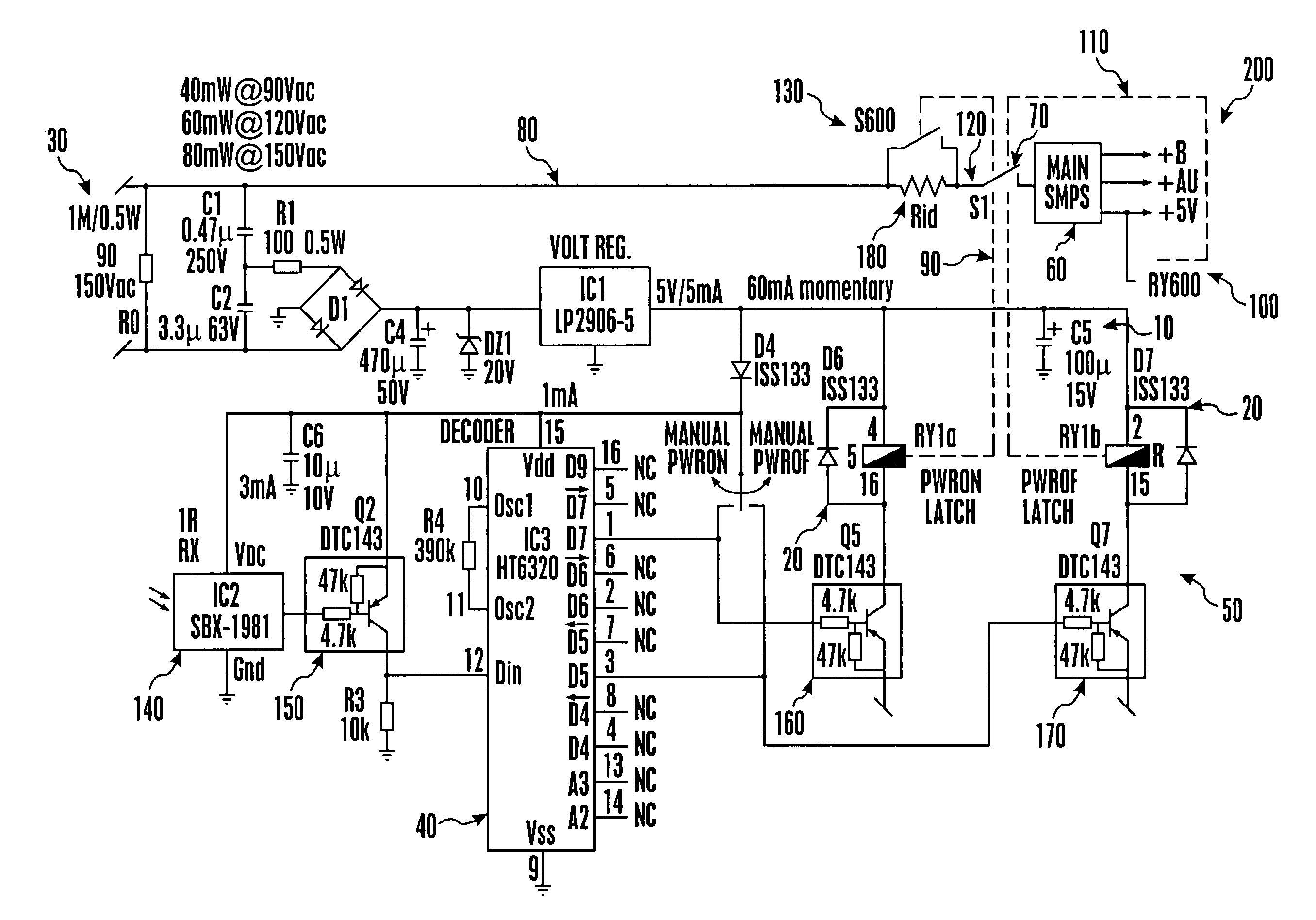
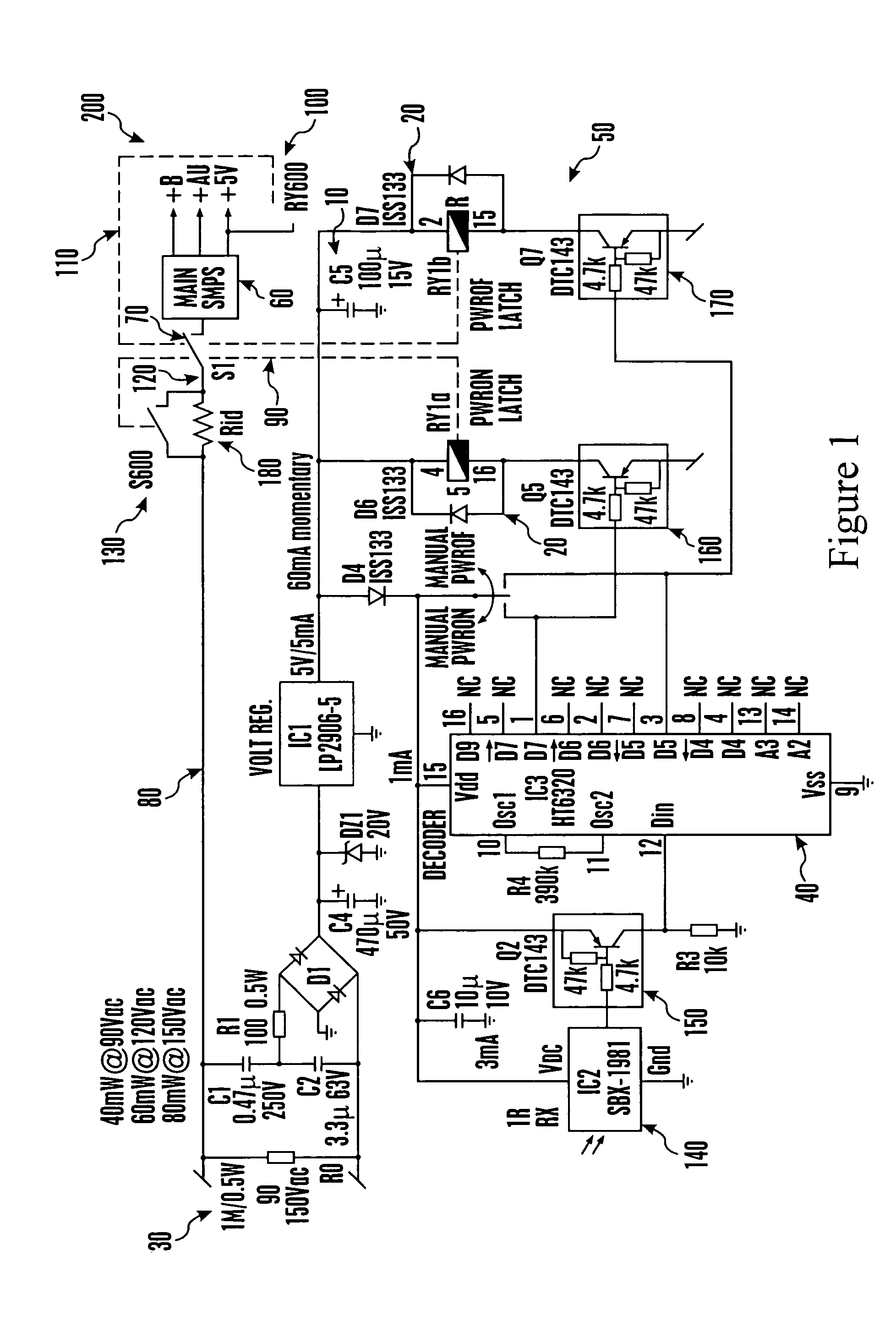
[0015]Turning now to FIG. 1, one embodiment of a micro-power operation system 200 is shown. Micro-power operation system 200 includes a micro-power stand-by power supply circuit 50 and a main power supply circuit 60. In one embodiment, stand-by power supply circuit 50 includes at least one capacitor 10 in electrical communication with at least one stand-by relay 20. Capacitor 10 is electrically connected to, and receives power from, an AC line 30 to supply power to stand-by power supply circuit 50 and stand-by relay 20. Stand-by relay 20 is also electrically connected to a MOS decoder 40.

[0016]In one embodiment, at l...


PUM


Abstract

A micro-power stand-by system is provided which minimizes power supplied to and the utilization of a stand-by power supply circuit and the resultant production of electro-magnetic interference (EMI) during normal electronic device operation. In one embodiment, the stand-by power supply circuit includes at least one capacitor in electrical communication with at least one stand-by relay, with the capacitor electrically connected to an AC line. The capacitor powers the stand-by power supply circuit and the stand-by relay. At least one switch is located a prearranged distance from a main power supply circuit, and is electrically connected to the AC line and the stand-by relay to provide normal operation for the main power supply circuit. In another embodiment, the switch includes a stand-by switch and a main power switch which provide an inrush current limiting resistor during initial power-on for safety reasons and a bypass of the inrush current limiting resistor during normal operation, respectively.

Description

[0001]This application incorporates herein by reference Patent Application Ser. No. 10 / 005668, by John Libera, entitled STAND-BY POWER SUPPLY SHUTDOWN AT POWER ON, filed concurrently herewith.COPYRIGHT NOTICE[0002]A portion of the disclosure of this patent document contains material which is subject to copyright protection. The copyright owner has no objection to the facsimile reproduction of the patent document or the patent disclosure, as it appears in the Patent and Trademark Office patent file or records, but otherwise reserves all copyright rights whatsoever.FIELD OF THE INVENTION[0003]This invention relates generally to the field of power supply circuits. More particularly, this invention relates to a micro-power stand-by system and method for operation.BACKGROUND OF THE INVENTION[0004]Power supply circuits are utilized in electronic devices to provide continuous operation. For example, a television set utilizes a power supply circuit to provide electrical power for reception ...

Claims


Application Information

Patent Timeline
Patent Type & Authority Patents(United States)
IPC IPC(8): H04N5/63H02J9/00
CPCH02J9/005H02M7/05
Inventor LIBERA, JOHN
Owner SATURN LICENSING LLC
Why Eureka
Try Eureka