Core-type furnace

a furnace and core technology, applied in the field of induction furnace crucible and hearth, can solve the problem that the frequency of electric arcs above 100 khz is not at all sufficient, and achieve the effect of perfect electric protection

Inactive Publication Date: 2006-02-07
COMMISSARIAT A LENERGIE ATOMIQUE ET AUX ENERGIES ALTERNATIVES +2
View PDF10 Cites 17 Cited by
  • Summary
  • Abstract
  • Description
  • Claims
  • Application Information

AI Technical Summary

Benefits of technology

[0013]To avoid the occurrence of electric arcs, the solution chosen consists of coating the metallic segments forming the crucible and metallic boxes of the hearth on one or all their faces with a ceramic electric insulation layer: at least on the inner and side surfaces of the segments facing one another to eliminate electric arcs or, depending upon chemical and electrical attack, on all the faces including the head, foot and surface facing the exterior of the furnace. These ceramic coatings are provided in addition to the electrical insulation placed between the segments of the crucible and the hearth boxes, and they provide perfect electric

Problems solved by technology

While a chamfer on the sharp edges of the segments may help towards satisfactory depositing of the ceramic electric insulation on the segment faces, this is not at all sufficient to withstand the occurrence of electric arcs at frequencies above 100 kHz be

Method used


Image

  • Core-type furnace
  • Core-type furnace
  • Core-type furnace

Examples


Embodiment Construction

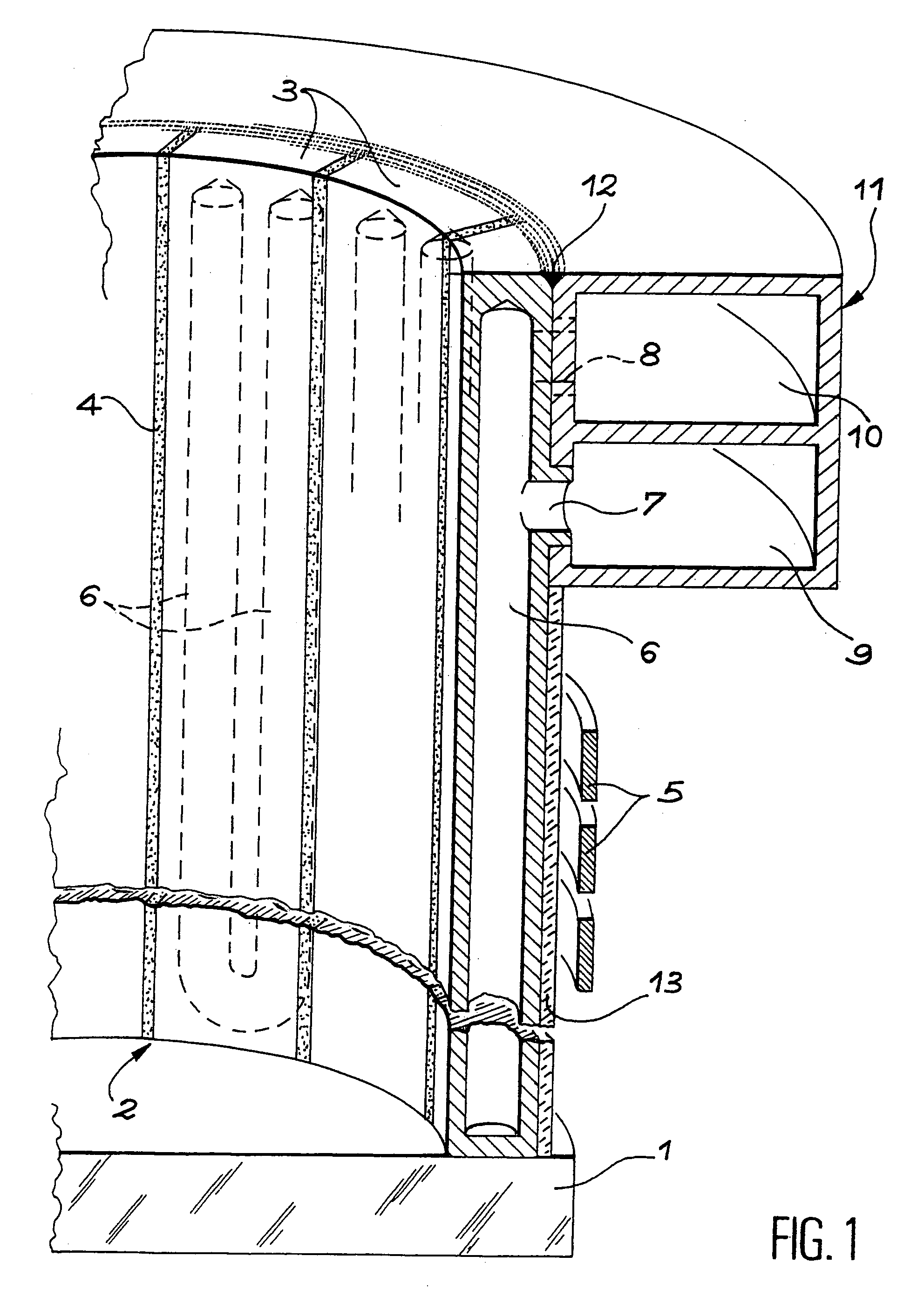
[0025]With reference to FIG. 1, a crucible comprises a hearth in refractory concrete which carries reference 1, a side wall carrying reference 2, its segments in stainless steel carrying reference 3, intermediate layers of electric insulation reference 4, and inductor coils reference 5. The details of construction and arrangement of these parts comply with the aforesaid description. Side part 2 is only partly shown, but it is clear that it extends over a circle or complete turn as for any other crucible including those of the invention. A cooling circuit 6 is hollowed out of each of segments 3, which extends over practically their entire height and is here made up of a pair of parallel ducts meeting at the bottom of segments 3 (only one of these ducts being visible in the cross-section). By means of pierced inlets and outlets 7 and 8 for the cooling liquid, the ducts communicate outside of segments 3 and lead to superimposed collectors 9 and 10 belonging to the same flange 11 to whi...


PUM


Abstract

Vertical segments of a side wall of a crucible for an induction furnace are assembled at an adjustable, invariable position by screws screwed into tapped holes of a flange common to all segments. A precise assembly is thus obtained producing no deformation and no internal stresses. The segments are coated with a ceramic coating for their protection and to prevent formation of electric arcs. Junction edges of faces are rounded to achieve the same effect. Water cooling boxes of the lower furnace hearth are similarly constructed. The apparatus can, as an example, be applied to vitrification techniques.

Description

BACKGROUND OF THE INVENTION[0001]1. Field of the Invention[0002]The subject matter of this invention is an induction furnace crucible and hearth for the incineration and vitrification of organic matter, the vitrification of radioactive and non-radioactive waste, the vitrification of hazardous waste and the fusing of refractory bodies.[0003]2. Description of the Related Art[0004]The structure of said furnaces essentially comprises a hearth in refractory concrete including cooling water circuits on which a side wall is arranged called the crucible, surrounded by an inductive coil in which an electric current circulates at frequencies higher than 100 kHz which is the source of the power produced inside the crucible to melt the matter therein. These furnaces are chiefly used for the incineration and vitrification of organic matter, the vitrification of radioactive or non-radioactive waste and the fusion of refractory bodies. The industries likely to have recourse thereto are waste treat...

Claims


Application Information

Patent Timeline
IPC IPC(8): H05B6/22C04B41/87F27B14/06F27B14/08F27D1/00F27D1/12F27D11/06
CPCF27B14/061F27B2014/0843F27B14/06
Inventor BRUN, PATRICELACOMBE, JACQUESLADIRAT, CHRISTIANBOUSQUET, FRANCIS
Owner COMMISSARIAT A LENERGIE ATOMIQUE ET AUX ENERGIES ALTERNATIVES
Why Eureka
Try Eureka