Vehicle impact testing device
a technology of vehicle crash and test device, which is applied in vehicle testing, structural/machine measurement, instruments, etc., can solve the problems of time and effort required to carry out the test, excessive shock to the striker, etc., and achieve the effect of simple structure, reduced number of parts, and reduced cost of vehicle crash test apparatus
- Summary
- Abstract
- Description
- Claims
- Application Information
AI Technical Summary
Benefits of technology
Problems solved by technology
Method used
Image
Examples
first embodiment
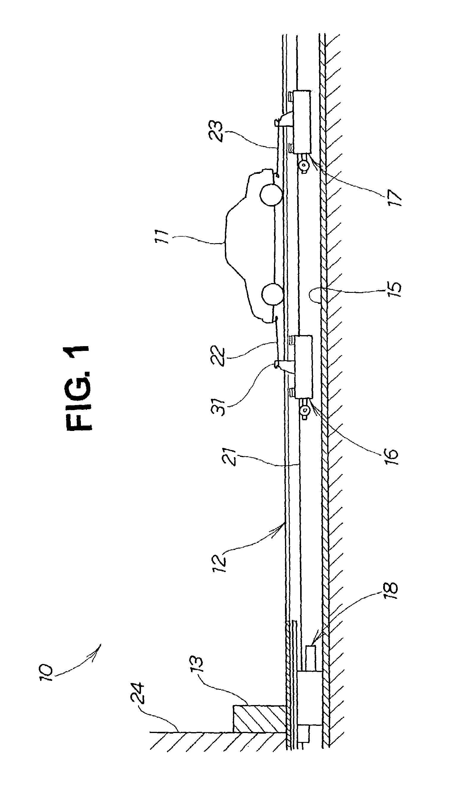
[0084]A number of preferred embodiments of the invention will now be described, on the basis of the accompanying drawings. FIG. 1 through FIG. 11 show a vehicle crash test apparatus of the invention.
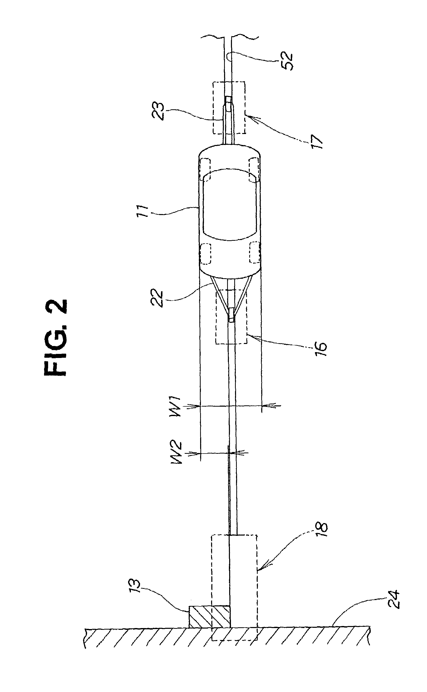
[0085]Referring toFIG. 1, the vehicle crash test apparatus 10 of this first embodiment has a road surface 12 on which travels a vehicle 11 serving as a test vehicle. At one end of this road surface 12 there is a barrier 13. A channel 15 is provided below the road surface 12. A towing device 16 for pulling the vehicle 11 is mounted movably in the channel 15. An auxiliary towing device 17 for applying a tensile force to the rear of the vehicle 11 to raise the straightness of travel of the vehicle 11 is also mounted movably in the channel 15. To stop the towing device 16 and the auxiliary towing device 17, a braking device 18 is provided in the channel 15 roughly below the barrier 13. To move the towing device 16 and the auxiliary towing device 17 toward the barrier 13, a cable 21 which can...
second embodiment
[0113]Next, a vehicle crash test apparatus according to the invention will be described, on the basis of FIG. 12 through FIG. 26C.
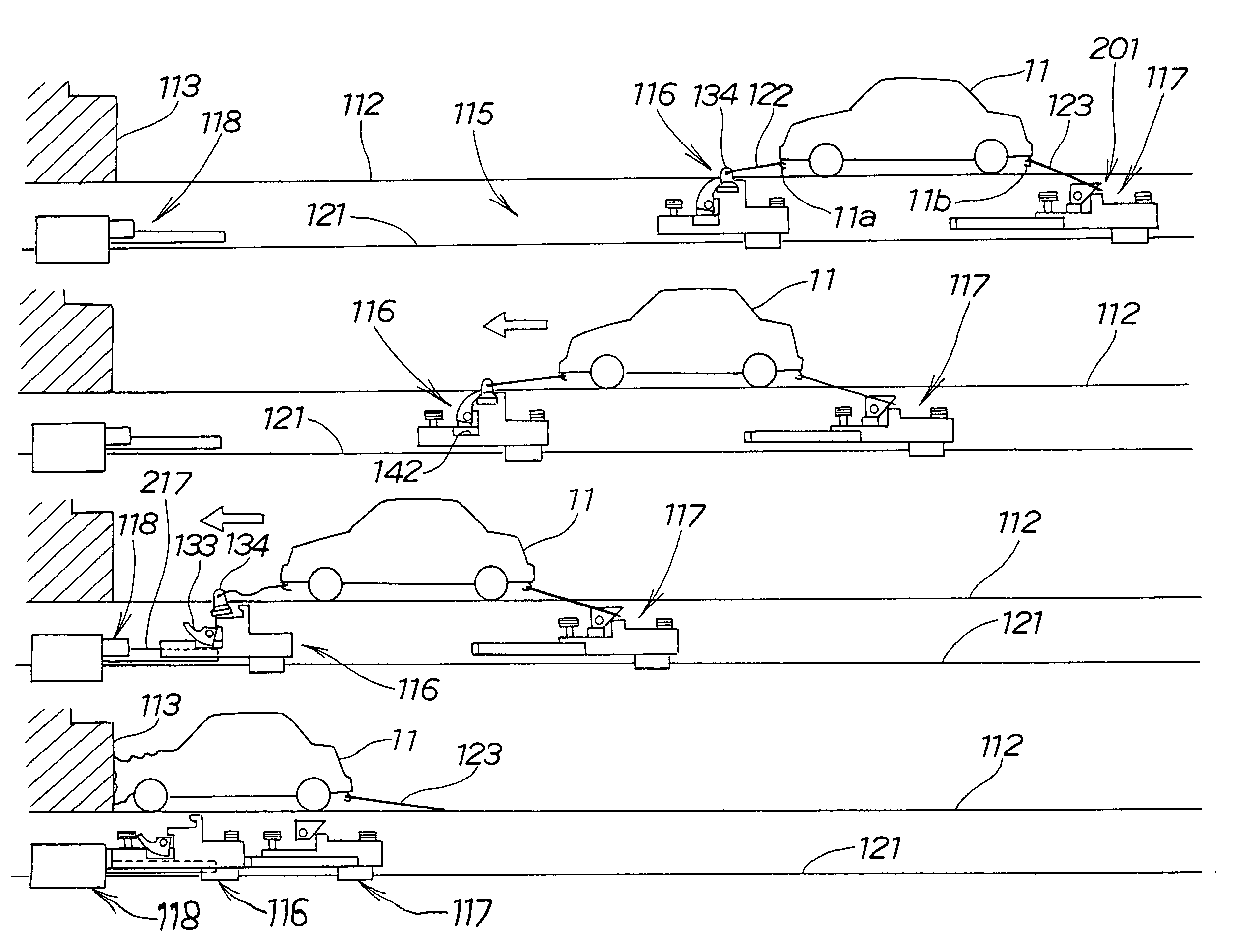
[0114]The vehicle crash test apparatus 100 of a second embodiment shown in FIG. 12 has a barrier 113 for a test vehicle 11 to collide with. The test vehicle 11 is pulled toward this barrier 113 by a towing device 116. An auxiliary towing device 117 is connected to the rear of the test vehicle 11. The towing device 116 and the auxiliary towing device 117 are moved toward the barrier 113 by a cable 121 which can be wound in by a winding device (not shown). When the towing device 116 has been moved toward the barrier 113, the towing device 116 is stopped by a braking device 118.
[0115]The test vehicle 11 travels on a road surface 112. The towing device 116 and the auxiliary towing device 14 are guided toward the barrier 113 by guide rails 126. The barrier 113 is fixed by a fixed wall 124. The test vehicle 11 and the towing device 116 are connected by a towing...
third embodiment
[0199]FIG. 36 through FIG. 44 show a vehicle crash test apparatus of the invention.
[0200]Referring to FIG. 36, the vehicle crash test apparatus 500 of this third embodiment has a road surface 512 on which travels a test vehicle 11. The road surface 512 has at one end thereof a barrier 513 for the test vehicle 11 to collide with. Below the road surface 512 is formed a channel 523. A towing device 515 for pulling the test vehicle 11 toward the barrier 513 along guide rails 514 is disposed in front of and below the test vehicle 11. A braking device 516 for stopping this towing device 15 is provided below the road surface 512 in the proximity of the barrier 513. A cable 517 is detachably connected to the towing device 515 and is drawn toward the barrier 513 by being wound onto a drum not shown in the drawings. The barrier 513 is fixed by a fixed wall 521. The test vehicle 11 is connected to the towing device 15 by a towing wire 522. The guide rails 514, the towing device 515, the brakin...
PUM
 Abstract
Description
Claims
Application Information
 - R&D
- Intellectual Property
- Life Sciences
- Materials
- Tech Scout
- Unparalleled Data Quality
- Higher Quality Content
- 60% Fewer Hallucinations
Browse by: Latest US Patents, China's latest patents, Technical Efficacy Thesaurus, Application Domain, Technology Topic, Popular Technical Reports.
© 2025 PatSnap. All rights reserved.Legal|Privacy policy|Modern Slavery Act Transparency Statement|Sitemap|About US| Contact US: help@patsnap.com


