
Vibration level sensor

a vibration level and sensor technology, applied in the direction of level indicators by physical variable measurement, liquid/fluent solid measurement, engine lubrication, etc., can solve the problem of unable to monitor the filling level, the principle of error recognition will fail, and the risk of a partial blockage of the oscillator remaining undetected

Active Publication Date: 2006-02-14
VEGA GRIESHABER GMBH & CO
View PDF4 Cites 20 Cited by
  • Summary
  • Abstract
  • Description
  • Claims
  • Application Information

AI Technical Summary

Benefits of technology

[0008]The object of the present invention is to create a filling level sensor in which the risk of locking onto an unsuitable frequency in the event of a partial blockage of the oscillator is diminished. A further object consis...

Problems solved by technology

The principle of error recognition will also fail if the tuning fork is detuned as a result of deposits on the tuning fork or mechanical damage to the tuning fork (as a result of erosion of the fork's tines, for example).
Its dependency upon the density and viscosity of the medium surrounding the mechanical oscillator can, however, be completely different in nature than that of an unhampered oscillator, making reliable monitoring of the filling level impossible.
This means the greater the distance between the frequencies of the individual oscillators for which such an oscillator may be used, the greater the risk that a partial blockage of the oscillator will remain undetected and that the filling level sensor could possibly provide false readings.

Method used


Image

  • Vibration level sensor
  • Vibration level sensor
  • Vibration level sensor

Examples


Embodiment Construction

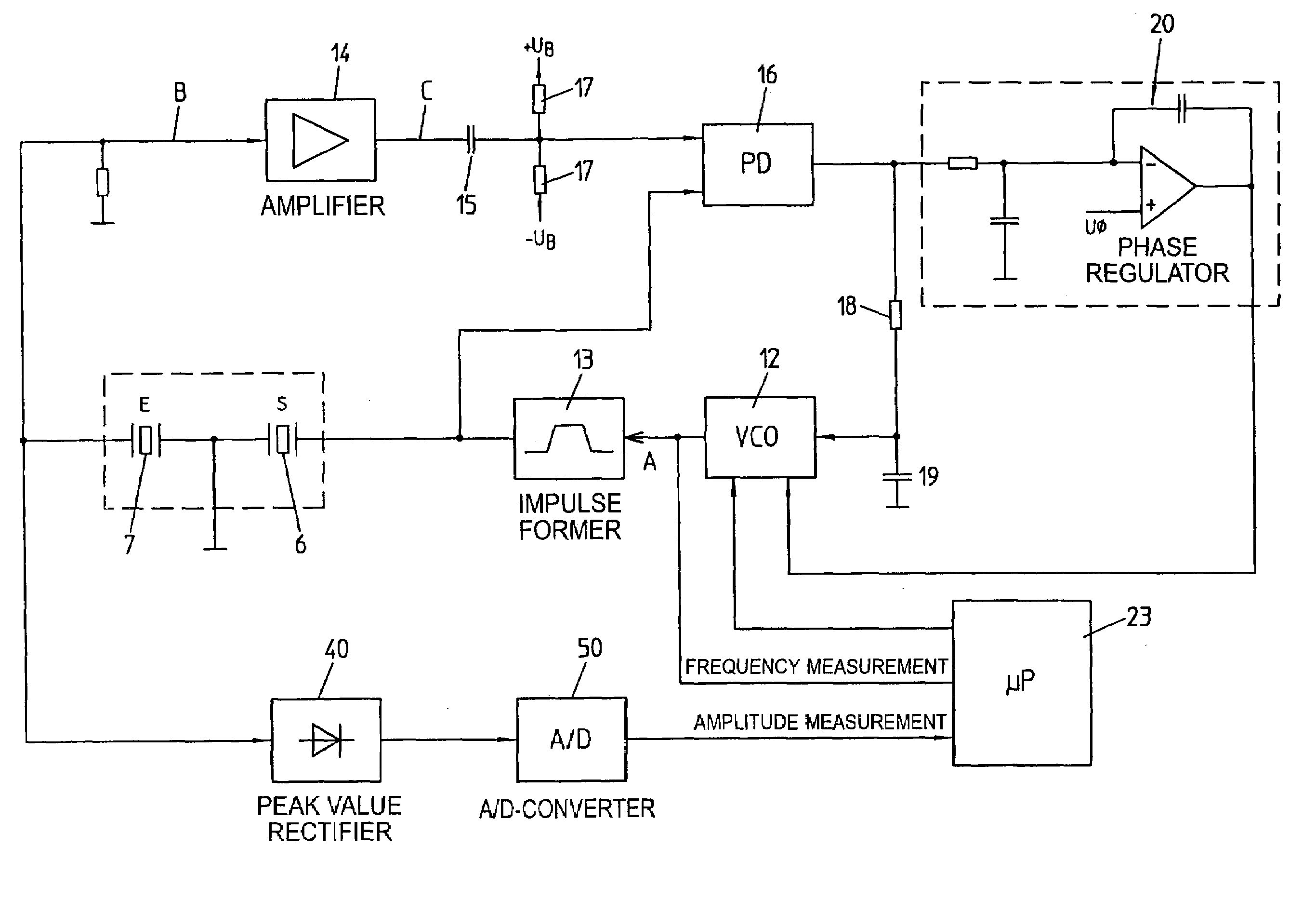
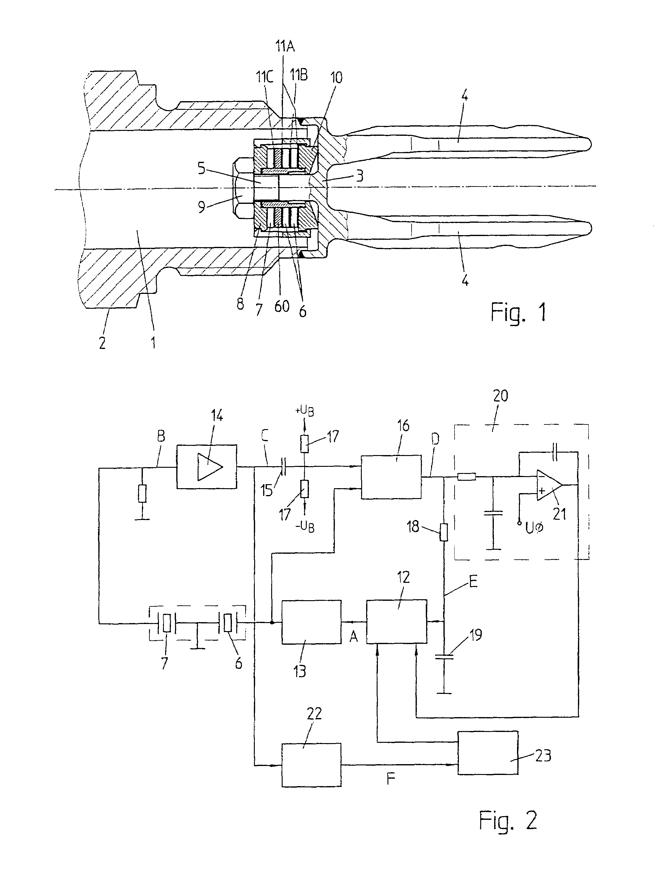
[0021]The measuring head shown in FIG. 1 is comprised of an insertable metallic housing 1, substantially beaker-shaped, which bears external threading 2 for screwing into an opening of a tank in which the filling level of a fluid is to be monitored. The bottom of the beaker is comprised of a membrane 3 that is capable of vibrating and bears two tuning fork tines 4 on its exterior, which is pointed into the interior of the tank, and a tie bolt 5 on its interior. Two piezo elements 6, 7 are arranged in the form of a ring around tie bolt 5. In order to achieve a higher transmission amplitude, piezo element 6 consists of two parallel-wired piezo rings that are separated by a metallic ring 111B. Piezo elements 6, 7 are pressed against a support ring 10, which is in direct contact with membrane 3, by a thrust collar 8 and a nut 9 that is screwed onto tie bolt 5. The electrical separation of piezo elements 6,7, which function as transmitter and receiver, is accomplished by means of a ceram...


PUM


Abstract

A filling level sensor comprises a tunable electrical resonant circuit, a mechanical oscillator that can be excited to resonance oscillation by the resonant circuit, and a control circuit for tuning the resonant circuit to a resonance frequency of the mechanical oscillator. A device for comparing the amplitude of the mechanical oscillator with a minimum value ascertains a malfunction of the mechanical oscillator if its amplitude falls below the minimum value.

Description

CROSS REFERENCE TO RELATED APPLICATIONS[0001]This application claims foreign priority under 35 U.S.C. §119 to German Patent Application Serial No. 102 42 970.7 filed Sep. 17, 2002, the entirety of which is hereby incorporated by reference herein.FIELD OF THE INVENTION[0002]The present invention relates to a filling level sensor with a tunable electrical resonant circuit, a mechanical oscillator that can be excited by the resonant circuit to tune the resonance and a control circuit for tuning the resonant circuit to a resonance frequency of the mechanical oscillator.BACKGROUND OF THE INVENTION[0003]A filling level sensor in the field of this invention is known from U.S. Pat. No. 5,895,848 and from German Patent DE 44 39 879 C1.[0004]The functional principle of such a filling level sensor rests on the fact that the resonance frequency of the mechanical oscillator changes depending upon the density and, to a slight degree, upon the viscosity of a medium in which the oscillator is immer...

Claims


Application Information

Patent Timeline
IPC IPC(8): G01F23/00G01F23/296
CPCG01F23/2967G01F23/80G01F25/20
Inventor WOEHRLE, SIEGBERT
Owner VEGA GRIESHABER GMBH & CO
Learn More