Valve arrangement including release valve

a valve arrangement and release valve technology, applied in the direction of servomotors, thin material handling, servomotor components, etc., can solve the problems of operator difficulty in simultaneously operating each release valve and maintaining the load in a relatively stationary position, and achieve the effect of convenient operation

Inactive Publication Date: 2006-02-14
ALADDIN ENG & MFG
View PDF38 Cites 14 Cited by
  • Summary
  • Abstract
  • Description
  • Claims
  • Application Information

AI Technical Summary

Benefits of technology

[0023]One advantage of the present invention is that, when the release valve is operated to release fluid pressure, the piston is not allowed to move so that the load is maintained in a substantially stationary position.
[0024]Another advantage of the present invention is that, because the release valve simultaneously controls fluid flow from the first and second ports, the load does not drift when the release valve is operated.
[0025]Yet another advantage of the present invention is that, because a single release valve releases fluid pressure simultaneously from the first and second ports, the release valve is easier to operate to maintain the piston and the load in the substantially stationary position.
[0026]A further advantage of the present invention is that the release valve prevents the first and second valves from being in fluid communication during operation of the valve arrangement and during operation of the release valve.
[0027]Other features and advantages of the invention will become apparent to those skilled in the art upon review of the following detailed description, claims and drawings.

Problems solved by technology

One independent problem with the above-described valve arrangement having a single locking valve and a single release valve connected to one port of the cylinder assembly is that, when the release valve is operated to release the fluid pressure from the system, the piston moves relative to the cylinder, and, therefore, the load also moves.
One independent problem with the above-described valve arrangement having a locking valve and a release valve connected to each port is that each release valve operates independently, allowing the position of the piston and the load to drift as fluid pressure is released from the system.
Another independent problem with the above-described valve arrangement having a locking valve and a release valve connected to each port is that, because each release valve is operated independently, an operator has difficulty simultaneously operating each release valve and maintaining the load in a relatively stationary position.
An independent problem with designing a release valve which controls the release of fluid pressure from both ports, simultaneously, is that, during operation of the valve assembly and during operation of the release valve, the release valve must prevent each locking valve connected to the corresponding port from being in fluid communication with the other locking valve.

Method used


Image

  • Valve arrangement including release valve
  • Valve arrangement including release valve
  • Valve arrangement including release valve

Examples


Embodiment Construction

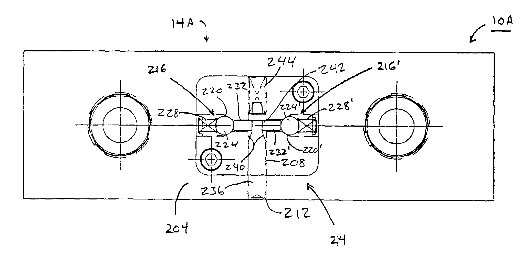
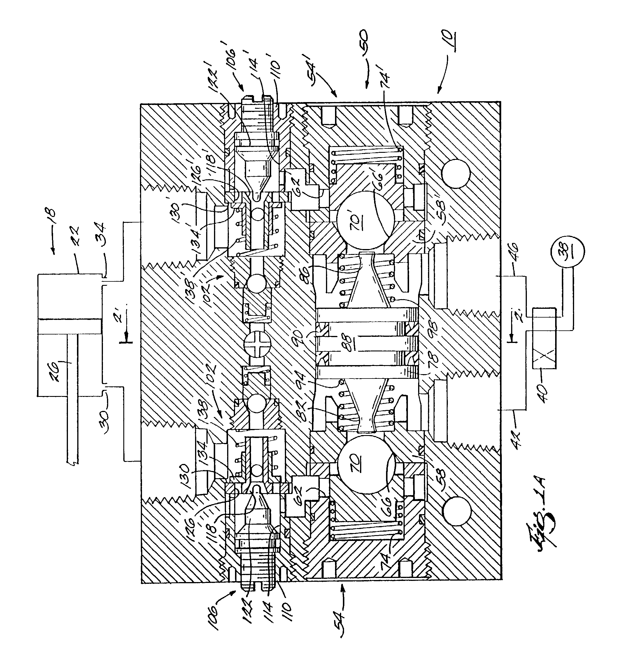
[0037]A valve arrangement 10 including a release valve 14 embodying the invention is illustrated in FIGS. 1A and 2. The valve arrangement 10 is used to control a fluid-operated device, such as a cylinder assembly 18. The cylinder assembly 18 includes a cylinder 22 which slideably houses a piston 26 for movement between an extended position (to the left in FIG. 1A) and a retracted position (to the right in FIG. 1A) to move a load (not shown), if provided. The cylinder assembly 18 also includes a first port 30 and a second port 34. The valve arrangement 10 fluidly connects a source 38 of fluid pressure, preferably air pressure, to the cylinder assembly 18 and is operable to control movement of the piston 26 and to, therefore, control movement of the load, upon interruption of fluid pressure supplied to the cylinder assembly 18. It should be understood that, in other constructions (not shown), the valve arrangement 10 may be used to control other fluid-operated devices.

[0038]A directio...


PUM


Abstract

A valve arrangement including a release valve. The valve arrangement controls a cylinder assembly including a first port and a second port, and a cylinder slideably housing a piston for movement between an extended position and a retracted position. The valve arrangement includes a valve assembly in fluid communication with the source of fluid pressure and with the first port and the second port to control fluid flow between the source and the first port and second port, and a release valve fluidly connected to the first port and to the second port, the release valve being operable to control flow of fluid from the first port and from the second port. The release valve is movable between a closed position and an open position. Fluid flows from both the first port and the second port simultaneously when the release valve member is in the open position.

Description

RELATED APPLICATIONS[0001]The present Application is a continuation-in-part of U.S. patent application Ser. No. 09 / 460,443, filed Dec. 13, 1999, now issued as U.S. Pat. No. 6,477,937.FIELD OF THE INVENTION[0002]The invention relates to fluid-operated devices and, more particularly, to a valve arrangement including a release valve for controlling a fluid-operated device.BACKGROUND OF THE INVENTION[0003]A cylinder assembly is a typical fluid-operated device. Generally, the cylinder assembly includes a cylinder having first and second ports and slideably housing a piston for movement between extended and retracted positions to move a load. To control movement of the piston and the load, a valve assembly is provided in fluid communication with a source of fluid pressure and with one or both of the ports of the cylinder assembly. The valve assembly may include a locking valve which operates to control movement of the piston upon interruption of the source of fluid pressure.[0004]In one c...

Claims


Application Information

Patent Timeline
Patent Type & Authority Patents(United States)
IPC IPC(8): F15B13/04F15B11/04F15B11/044F15B13/01
CPCF15B11/0413F15B11/044F15B13/01F15B2211/30515F15B2211/72F15B2211/41536F15B2211/45F15B2211/7053F15B2211/40515Y10T137/2567Y10T137/87241
Inventor HORN, EDWARD R.DOWD, ROBERT E.THORNTON, THOMAS J.
Owner ALADDIN ENG & MFG
Why Eureka
Try Eureka