Expandable hanger and packer

a technology of expandable tubular and expandable tubular, which is applied in the direction of hose connection, borehole/well accessories, mechanical equipment, etc., can solve the problems of occupying valuable annular space in the wellbore, relative movement of the necessary parts, and the body of the packer necessarily requires the wellbore space, so as to reduce the amount of radial force, increase the and increase the sealing capacity of the expandable tubular

Inactive Publication Date: 2006-02-14
WEATHERFORD TECH HLDG LLC
View PDF81 Cites 38 Cited by
  • Summary
  • Abstract
  • Description
  • Claims
  • Application Information

AI Technical Summary

Benefits of technology

[0015]The present invention generally relates to an apparatus and method for engaging a first tubular and a second tubular in a wellbore. The present invention provides a tubular body formed on a portion of a first tubular. The tubular body is expanded so that the outer surface of the tubular body is in frictional contact with the inner surface of a surrounding second tubular. In one embodiment, the tubular body is modified by machining grooves and profile cuts into the surface, thereby reducing the amount of radial force required to expand the tubular body on the first tubular into the surrounding tubular.
[0016]The tubular body optionally includes hardened inserts, such as carbide buttons, for gripping the surrounding tubular upon contact. The gripping mechanism increases the capacity of the expanded tubular to support its weight and to serve as a hanger. In another aspect, the outer surface of the expandable tubular body optionally includes a pliable material such as an elastomer within grooves and profile cuts formed on the outer surface of the tubular for increasing the sealing capability of the expandable tubular. As the tubular is expanded, metal flow causes the profile cuts to close up, thereby causing the pliable material to extrude outward. This extrusion of the pliable material insures contact with the casing and improves the sealing characteristics of the interface between the expanded tubular and the casing.

Problems solved by technology

One problem associated with conventional sealing and slip systems of conventional downhole tools relates to the relative movement of the parts necessary in order to set the tools in a wellbore.
Additionally, the slip means takes up valuable annular space in the wellbore.
Also, the body of a packer necessarily requires wellbore space and reduces the bore diameter available for production tubing, etc.
This, in turn, enlarges the path through which both fluid and downhole tools may travel.
While expanding tubulars in a wellbore offers obvious advantages, there are problems associated with using the technology to create a hanger or packer through the expansion of one tubular into another.
Simply increasing the initial cross-sectional thickness of the tubular to compensate for the reduced tensile strength after expansion results in an increase in the amount of force needed to expand the tubular.
In another problem, the expansion of the tubular in the wellbore results in an ineffective seal between the expanded tubular and the surrounding wellbore.

Method used


Image

  • Expandable hanger and packer
  • Expandable hanger and packer
  • Expandable hanger and packer

Examples


Embodiment Construction

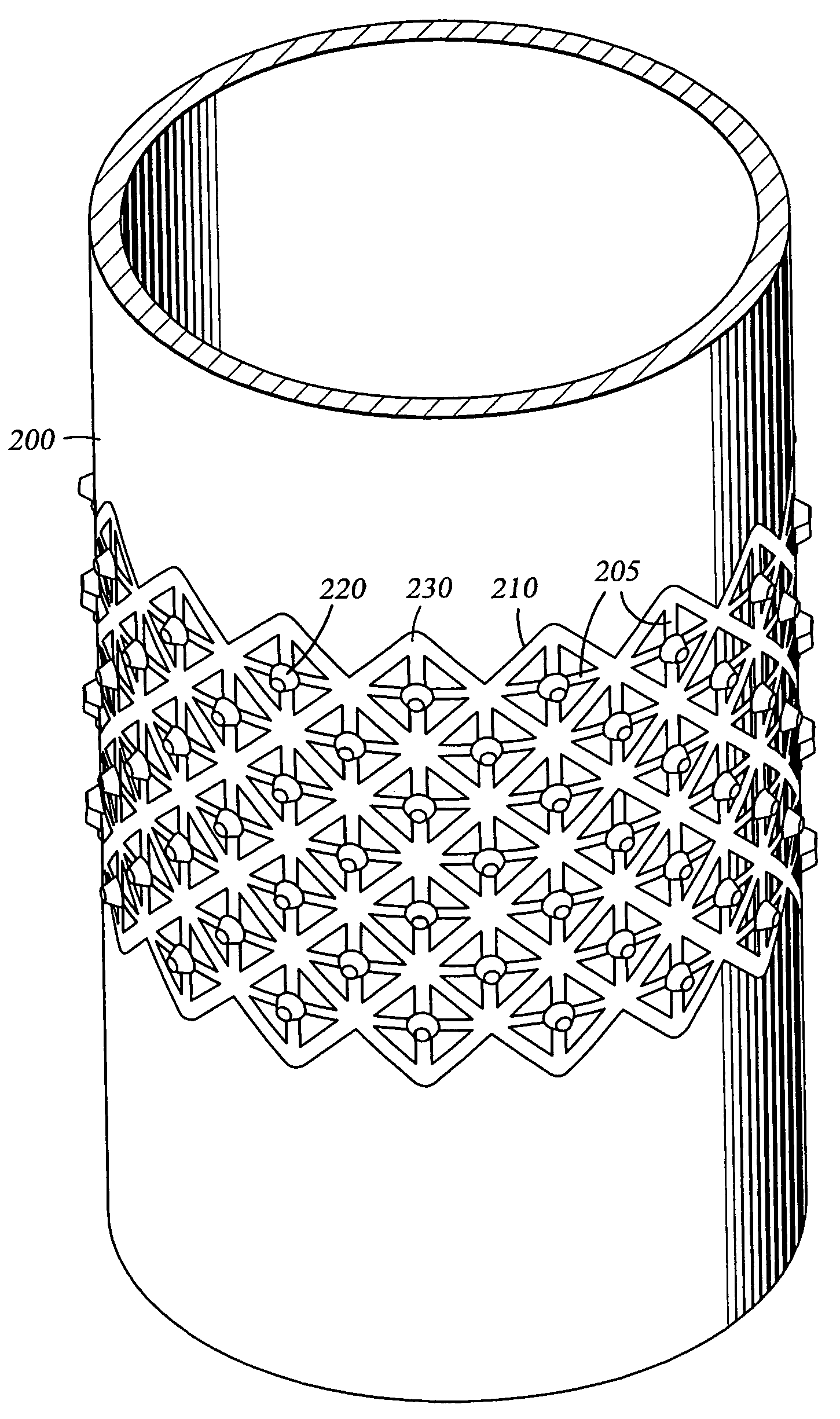
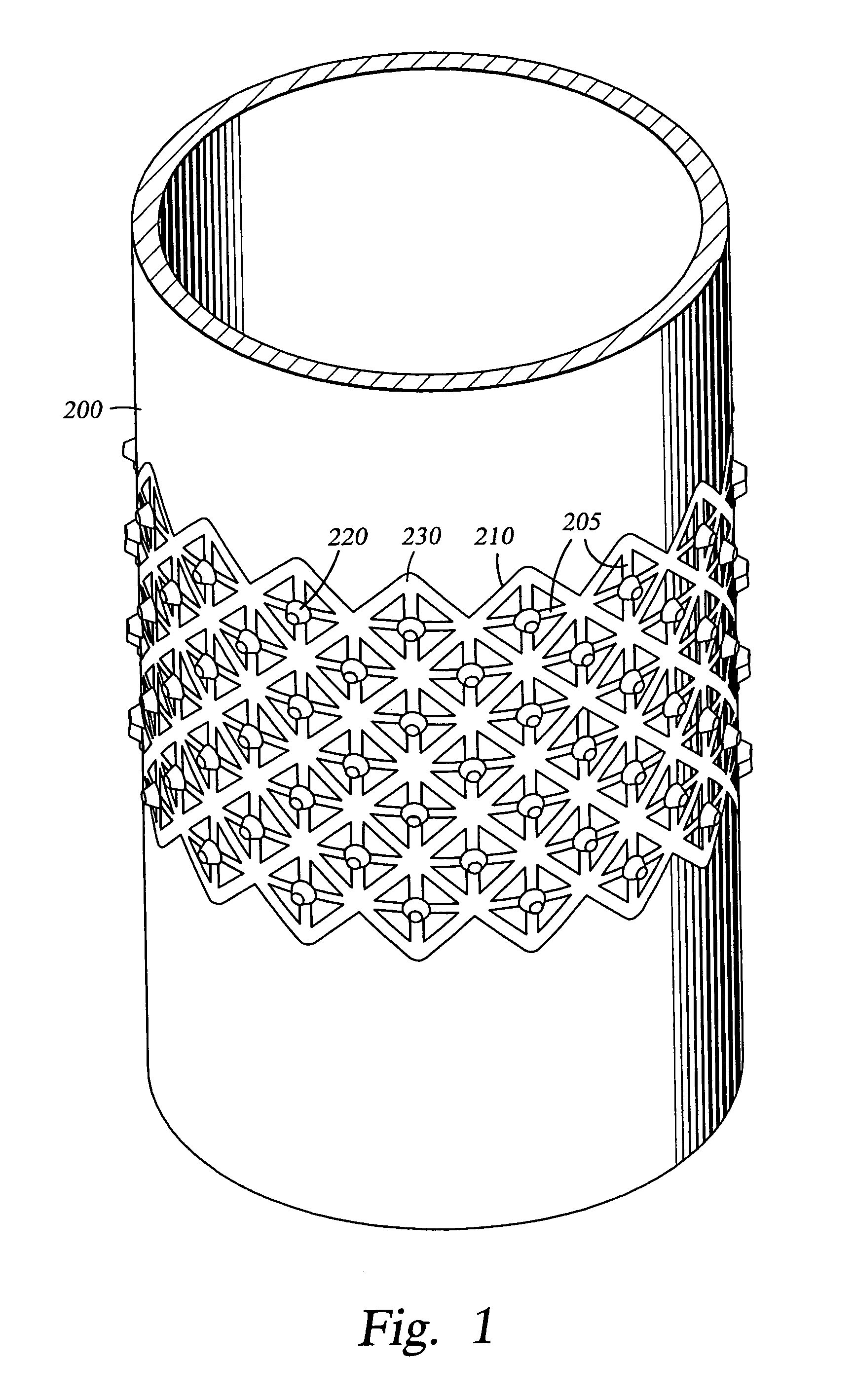
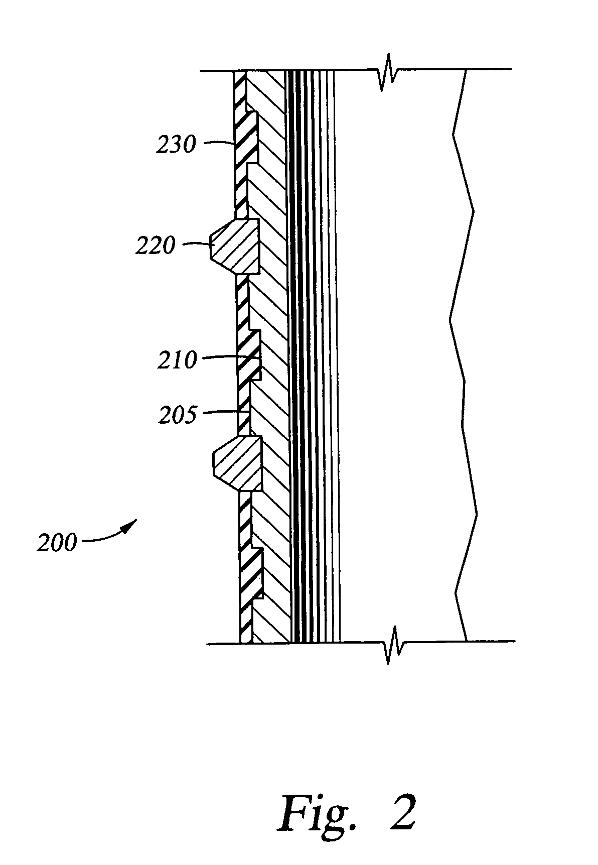
[0025]FIG. 1 is a perspective view of the apparatus of the present invention. The apparatus 200 defines a tubular body formed on a portion of a larger tubular. The tubular body 200 shown in FIG. 1 includes a series of relief grooves 210 and profile cuts 205 machined into the outer surface. However, it is within the scope of the present invention to machine some or all of the grooves 210 into the inner surface of the expandable tubular 200. The relief grooves 210 and profile cuts 205 serve to reduce the thickness of the tubular 200, thereby reducing the amount of material that must be plastically deformed in order to expand the tubular 200. This reduction in material also results in a reduction in the amount of force needed to expand the tubular 200.

[0026]As shown in FIG. 1, the grooves 210 are machined in a defined pattern. Employment of a pattern of grooves 210 serves to increase the tensile properties of the tubular 200 beyond those of a tubular with straight grooves simply cut ar...


PUM

PropertyMeasurementUnit
circumferenceaaaaaaaaaa
inner diameteraaaaaaaaaa
outer diameteraaaaaaaaaa

Abstract

A first tubular is disposed coaxially within a portion of a second, larger tubular. A portion of the first tubular is expanded into frictional contact with the second tubular, thereby creating a liner and a hanger. In one embodiment, a pattern of grooves and profile cuts are formed in the surface of a portion of the first tubular body. The grooves in one aspect define a continuous pattern about the circumference of the tubular body which intersect to form a plurality of substantially identical shapes, such as diamonds. The grooves and profile cuts serve to improve the tensile strength of the tubular body. At the same time, the grooves and profile cuts allow for expansion of the tubular body by use of less radial force. The grooves and profile cuts further provide additional frictional support for hanging the expanded tubular onto the inner surface of a surrounding second tubular.

Description

CROSS-REFERENCE TO RELATED APPLICATION[0001]This application is a continuation of U.S. patent application Ser. No. 10 / 132,424, filed Apr. 25, 2002, now U.S. Pat. No. 6,691,789 issued on Feb. 17, 2004, which is a continuation-in-part Ser. No. 09 / 949,986 filed Sep. 10, 2001 of issued U.S. Pat. No. 6,688,399, issued Feb. 10, 2004, which are incorporated in their entirety by reference herein.BACKGROUND OF THE INVENTION[0002]1. Field of the Invention[0003]The present invention relates to wellbore completion. More particularly, the invention relates to an apparatus and method for creating an attachment and a seal between two tubulars in a wellbore.[0004]2. Description of the Related Art[0005]In the drilling of oil and gas wells, a wellbore is formed using a drill bit that is urged downwardly at a lower end of a drill string. After drilling a predetermined depth, the drill string and bit are removed, and the wellbore is lined with a string of steel pipe called casing. The casing provides s...

Claims


Application Information

Patent Timeline
Patent Type & Authority Patents(United States)
IPC IPC(8): E21B17/00E21B43/00E21B43/10
CPCE21B43/103E21B43/106E21B43/105
Inventor JACKSON, STEPHENMAGUIRE, PATRICKTRAN, KHAI
Owner WEATHERFORD TECH HLDG LLC
Why Eureka
Try Eureka