Clutch release mechanism with a device for compensating for lack of precision in a friction clutch of a motor vehicle

a technology of friction clutch and release mechanism, which is applied in the direction of mechanical actuator clutch, clutch, mechanical apparatus, etc., can solve the problem of limiting the extent to which the outer ring can be deflected from its centered position, and achieve the effect of minimal space and minimal cos

Inactive Publication Date: 2006-02-14
ZF SACHS AG
View PDF4 Cites 4 Cited by
  • Summary
  • Abstract
  • Description
  • Claims
  • Application Information

AI Technical Summary

Benefits of technology

[0008]The sliding surface of the release mechanism described above is located on the outer ring of the release bearing in a plane perpendicular to the center axis of the guide sleeve, where, within certain limits, the release bearing can be pushed along the sliding of the sliding sleeve and thus moved out of a position coaxial with respect to the guide sleeve. Because the release bearing and the sliding sleeve are connected elastically together by a clamp, static friction is created, which stabilizes the release bearing when it has moved off-center. A ring-shaped stop is provided on the sliding surface of the sliding sleeve. The outer ring can make contact with this stop, which limits the extent to which the outer ring can be deflected from its centered position.
[0009]It is an object of the present invention to provide a clutch-release mechanism for actuating the release spring of a friction clutch of a motor vehicle which has a device for compensating for a tilt of the center axis of the friction clutch with respect to the center axis of a guide sleeve and / or for compensating for an offset of the above-mentioned center axes and / or for a wobbling eccentricity of the release spring. Preferably, such a mechanism occupies a minimal amount of space and has a minimal cost.

Problems solved by technology

The outer ring can make contact with this stop, which limits the extent to which the outer ring can be deflected from its centered position.

Method used


Image

  • Clutch release mechanism with a device for compensating for lack of precision in a friction clutch of a motor vehicle
  • Clutch release mechanism with a device for compensating for lack of precision in a friction clutch of a motor vehicle
  • Clutch release mechanism with a device for compensating for lack of precision in a friction clutch of a motor vehicle

Examples


Embodiment Construction

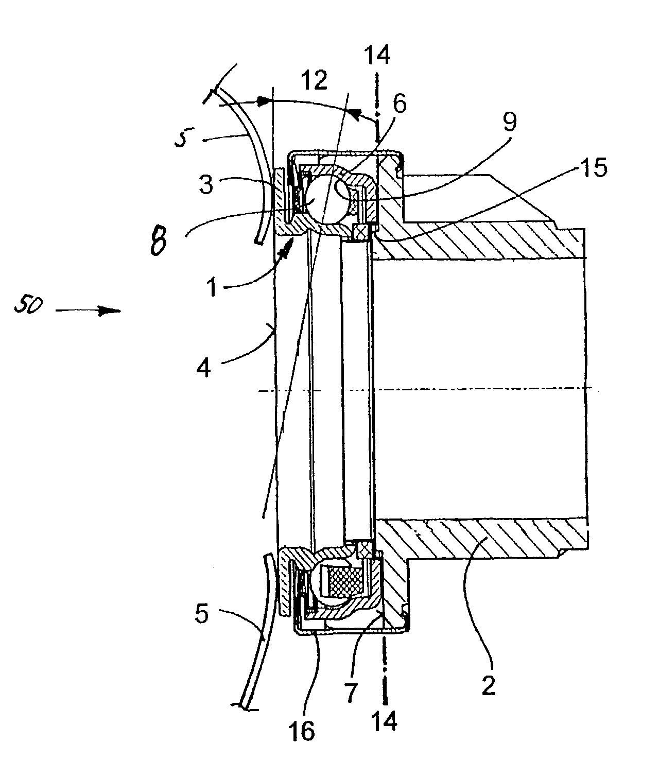
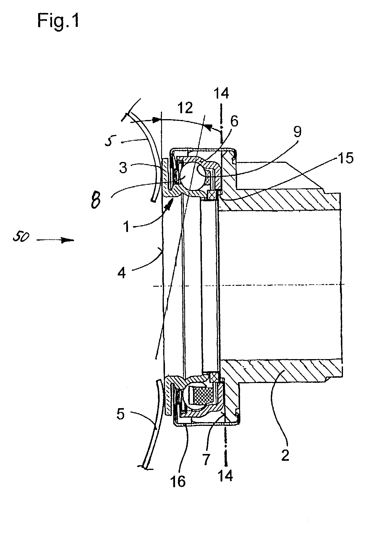
[0013]FIG. 1 shows a clutch-release mechanism 50 for actuating a friction clutch using a release spring 5. The release mechanism 50 has a release bearing 1, which is a ball bearing with an inner ring 3, balls 8, and an outer ring 6. The inner ring 3 rests by a contact surface 4 against the tongues of the release spring 5. The outer ring 6 has a sliding surface 7 indirectly or directly in common with a sliding sleeve 2 in a plane 14 transverse to the center axis of the release bearing 1. The sliding sleeve has a ring-shaped stop 15 for the outer ring 6 of the release bearing 1. A clamp 16 connects the release bearing 1 to the sliding sleeve 2 to form a structural unit.

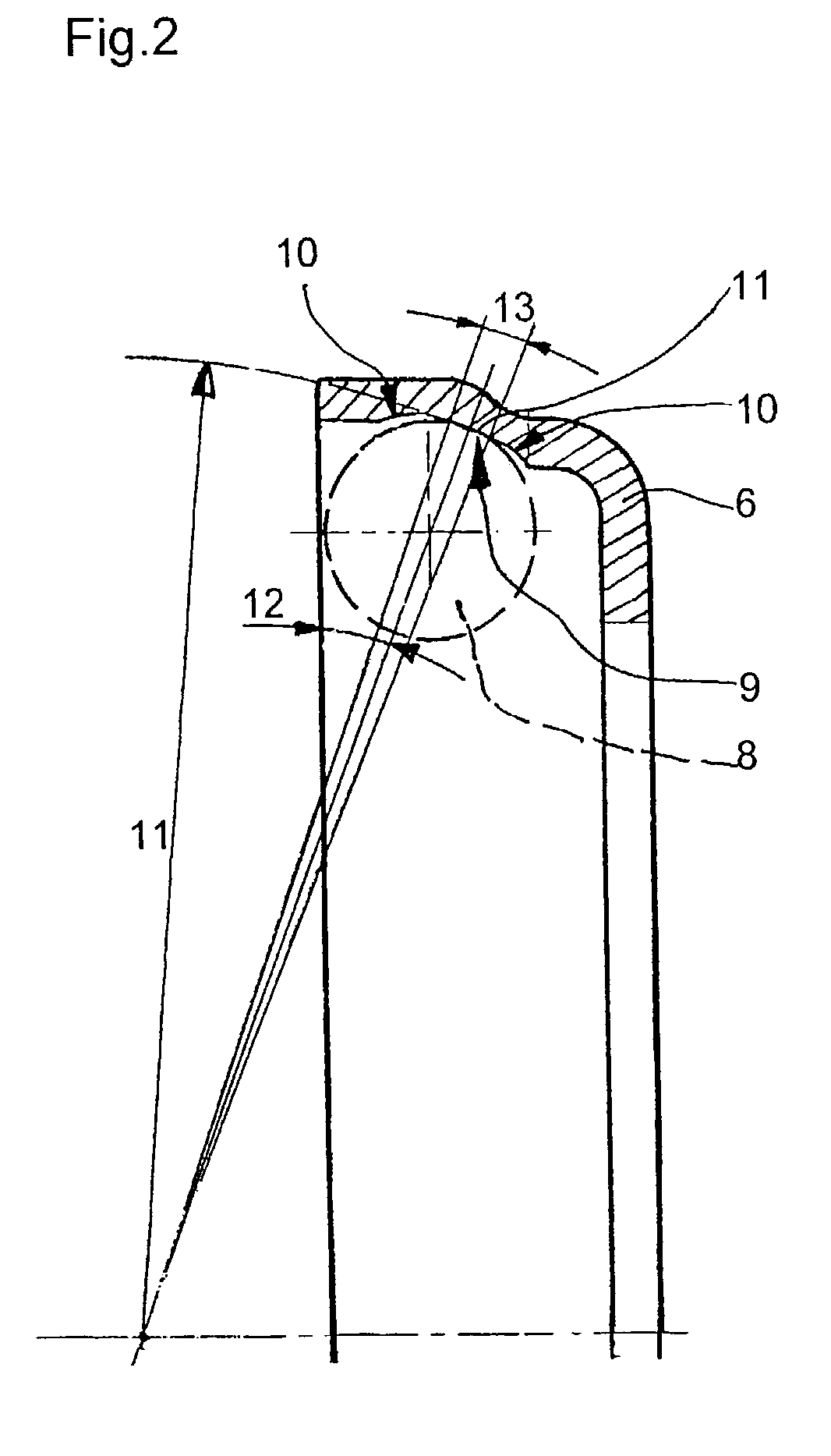
[0014]In FIG. 2, the outer ring 6 has a race 9 which includes a ring-shaped surface with a first race radius 10, an intermediate ring-shaped surface with a second race radius 11, and an inner ring-shaped surface, again with the first race radius 10. As the balls 8 rotate in the outer ring 6, they can move within a defle...


PUM


Abstract

A clutch-release mechanism for actuating the friction clutch of a motor vehicle, installed concentrically around a guide sleeve, includes a release bearing with an inner ring and an outer ring as well as a sliding sleeve. The inner ring is in working contact with a release spring of the friction clutch and the outer ring is in working contact with the sliding sleeve by way of a sliding surface, and the release mechanism has both a first device for compensating for a tilt of the center axis of the friction clutch with respect to the center axis of the guide sleeve and / or for a wobbling eccentricity of the release spring, and a second device for compensating for an offset between the above-mentioned center axes. The first device consists of a modified raceway for the balls, where the race has both a first race radius and a second race radius to form a surface in the form of a spherical segment, where differences between the angles of the release spring and of the release bearing are compensated. Because the raceway can be produced in any case with high precision in the outer ring and because the rolling contact of the parts is lubricated with grease and protected from the outside environment by seals, no additional components are required for the release mechanism, and there are no additional friction points to be lubricated and sealed.

Description

BACKGROUND OF THE INVENTION[0001]1. Field of the Invention[0002]The invention relates to a clutch release mechanism for actuating a friction clutch between an internal combustion engine and a transmission of a motor vehicle. This mechanism is installed as concentric assembly around a guide sleeve mounted on a transmission shaft, comprising a release bearing with an inner ring and an outer ring as well as a sliding sleeve, where one of the rings, preferably the inner ring, is in working connection with a release spring of the friction clutch and the outer ring is in working connection with the sliding sleeve. The assembled release mechanism has a first device for compensating for a tilt of the center axis of the friction clutch with respect to the center axis of the guide sleeve and / or for a wobbling eccentricity of the release spring and a second device for compensating for an offset between the previously mentioned center axes.[0003]2. Description of the Related Art[0004]DE 199 12 ...

Claims


Application Information

Patent Timeline
Patent Type & Authority Patents(United States)
IPC IPC(8): F16C19/10F16D23/14
CPCF16C19/163F16C23/08F16D23/14F16C2361/43F16C33/585F16C33/588
Inventor REUTER, KLAUS
Owner ZF SACHS AG
Why Eureka
Try Eureka