

Rotary manipulation type electronic component
a technology of electronic components and rotary manipulation, which is applied in the direction of resistors with sliding contact, contact mechanisms, adjustable resistors, etc., can solve the problems of resilient and deteriorating operation sensation, and achieve the effect of small heigh
- Summary
- Abstract
- Description
- Claims
- Application Information
AI Technical Summary
Benefits of technology
Problems solved by technology
Method used
Image

Examples
embodiment 1
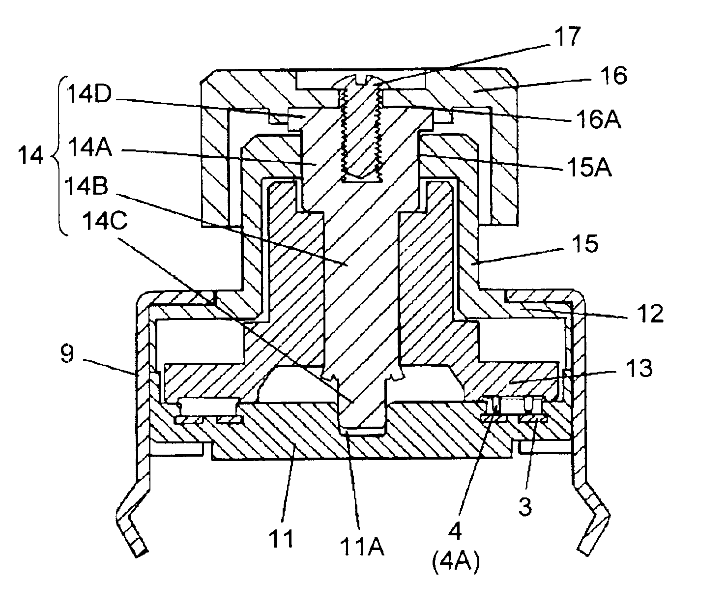
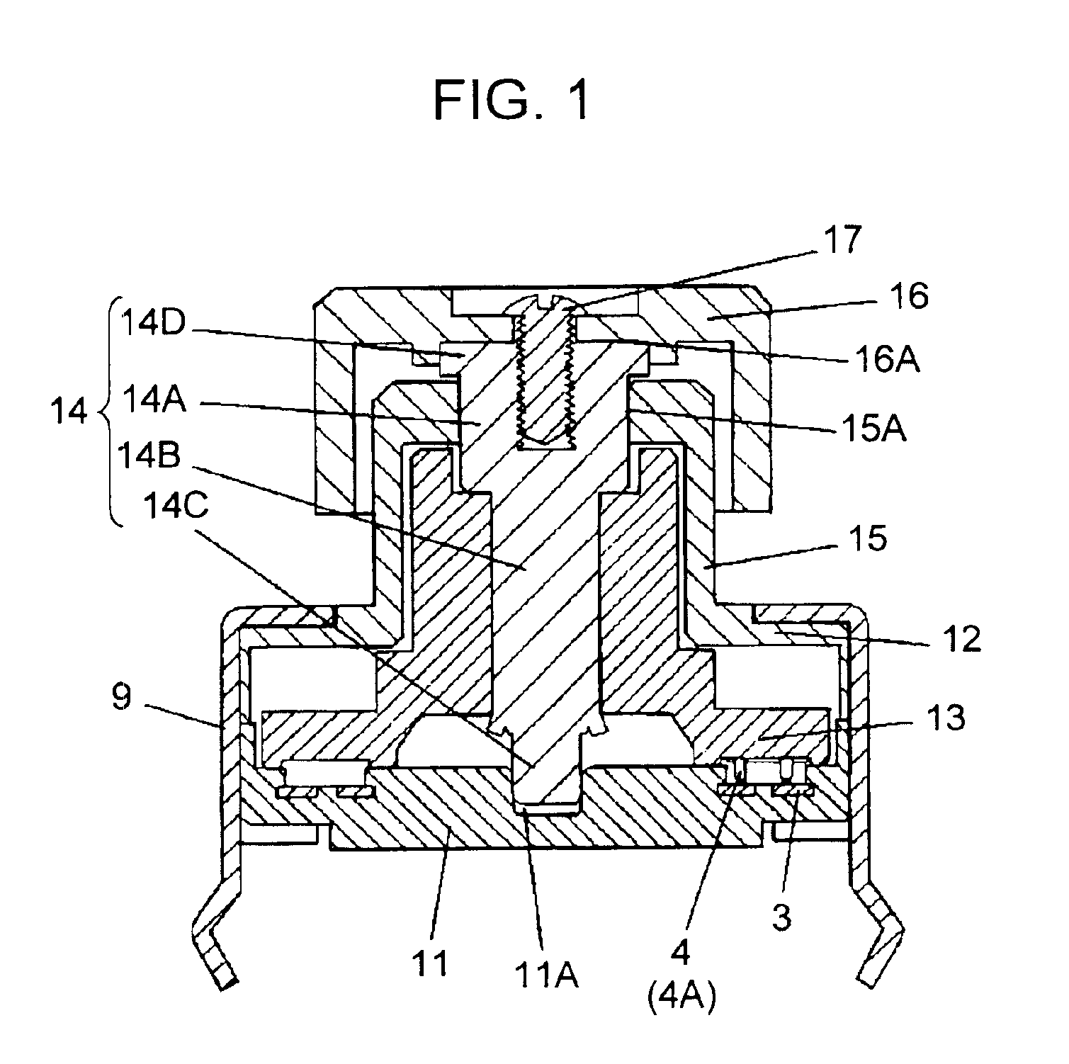
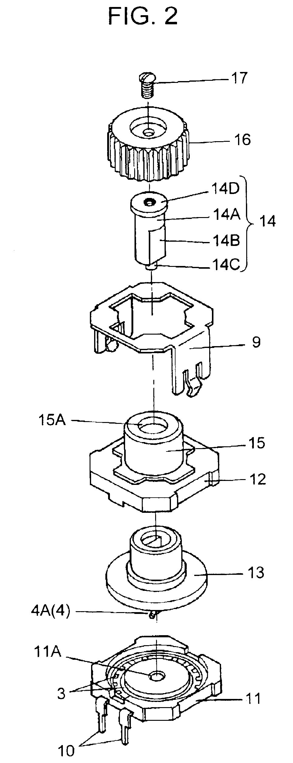
[0031]FIGS. 1 and 2 are a sectional view and an exploded perspective view, respectively, of a rotary encoder described in the embodiment 1 with reference to a rotary manipulation type electronic component of the present invention.
[0032]In the drawings, base 11 has concentric circular comb-like contact 3 as a fixed element on an inner top face thereof. The top face of the base is covered with case 12. Housed in a space formed by case 11 and base 12 is rotating body 13 that holds resilient contact 4 as a movable element for engaging with comb-like contact 3 to generate an electric signal. Rotating body 13 is joined by caulking and fixed to non-circular portion 14B in the middle of straight rod-like rotating shaft 14 to rotate together therewith. As for rotating shaft 14, upper circular portion 14A and lower circular portion 14C thereof are rotatably supported by top-end small circular portion (hereinafter referred to as a “first bushing”) 15A along the inner circumference of cylindric...
embodiment 2
[0042]In the embodiment 2, a description is provided of another example of the rotary manipulation type electronic component of the present invention by illustrating a rotary encoder.
[0043]In the description, constituents similar to those in the embodiment 1 have the same reference marks.
[0044]FIG. 6 is a sectional view of a rotary encoder as a rotary manipulation type electronic component in accordance with the embodiment 2 of the present invention.
[0045]As shown in FIG. 6, the rotary encoder of this embodiment has a method of supporting rotating body 21 different from that of the embodiment 1.
[0046]Upper circular portion 22A and lower circular portion 22C of straight rod-like rotating shaft 22 are rotatably supported by first bushing 15A along the inner circumference of cylindrical barrel portion 15 in the upper portion of case 12, and second bushing 11A in the top face of base 11, respectively. Cap-shaped knob 16 is disposed to cover barrel portion 15 and top end 22D of rotating ...
embodiment 3
[0055]In the embodiment 3, a description is provided of another example of the rotary manipulation type electronic component of the present invention by illustrating a rotary encoder.
[0056]In the description, constituents similar to those in the embodiment 2 have the same reference marks.
[0057]FIG. 7 is a front sectional view and FIG. 8 is an exploded perspective view of a rotary encoder in accordance with the embodiment 3 of the present invention.
[0058]As shown in FIG. 7, some structures of the rotary encoder of the third exemplary embodiment are similar to those of the embodiment 2. For the rotary encoder of the embodiment 3, in addition to these structures, rotating shaft 24 is supported to be movable vertically, and dome-like switch (push switch) 28 for generating a second electric signal corresponding to vertical movement of rotating shaft 24 is provided below base 25.
[0059]Upper circular portion 24A and lower circular portion 24C of straight rod-like rotating shaft 24 are rota...
PUM
 Abstract
Description
Claims
Application Information