Pressure regulating reservoir and vehicular braking apparatus using it

a technology of pressure regulation reservoir and braking apparatus, which is applied in the direction of braking systems, etc., can solve the problems of assembly errors, small resistance, and unnecessary countermeasures to lower slide resistan

Inactive Publication Date: 2009-06-09
ADVICS CO LTD
View PDF9 Cites 55 Cited by
  • Summary
  • Abstract
  • Description
  • Claims
  • Application Information

AI Technical Summary

Benefits of technology

[0014]It is an object of the present invention to provide a pressure regulating reservoir easily capable of controlling a lift amount of a ball valve, and a vehicular brake apparatus using it.

Problems solved by technology

However, the slide resistance becomes small in the case of a resin piston J6, making the countermeasure to lower slide resistance unnecessary.
However, assembly errors may occur when integrating the shaft J7 into the piston J6, or when assembling the unit including the ball valve J3, the valve seat J4 and the filter component J5 to the passage J13.
The effects of these assembly errors, as well as variations in the dimensional accuracy of each component, often make it difficult to achieve the above control.

Method used


Image

  • Pressure regulating reservoir and vehicular braking apparatus using it
  • Pressure regulating reservoir and vehicular braking apparatus using it
  • Pressure regulating reservoir and vehicular braking apparatus using it

Examples


first embodiment

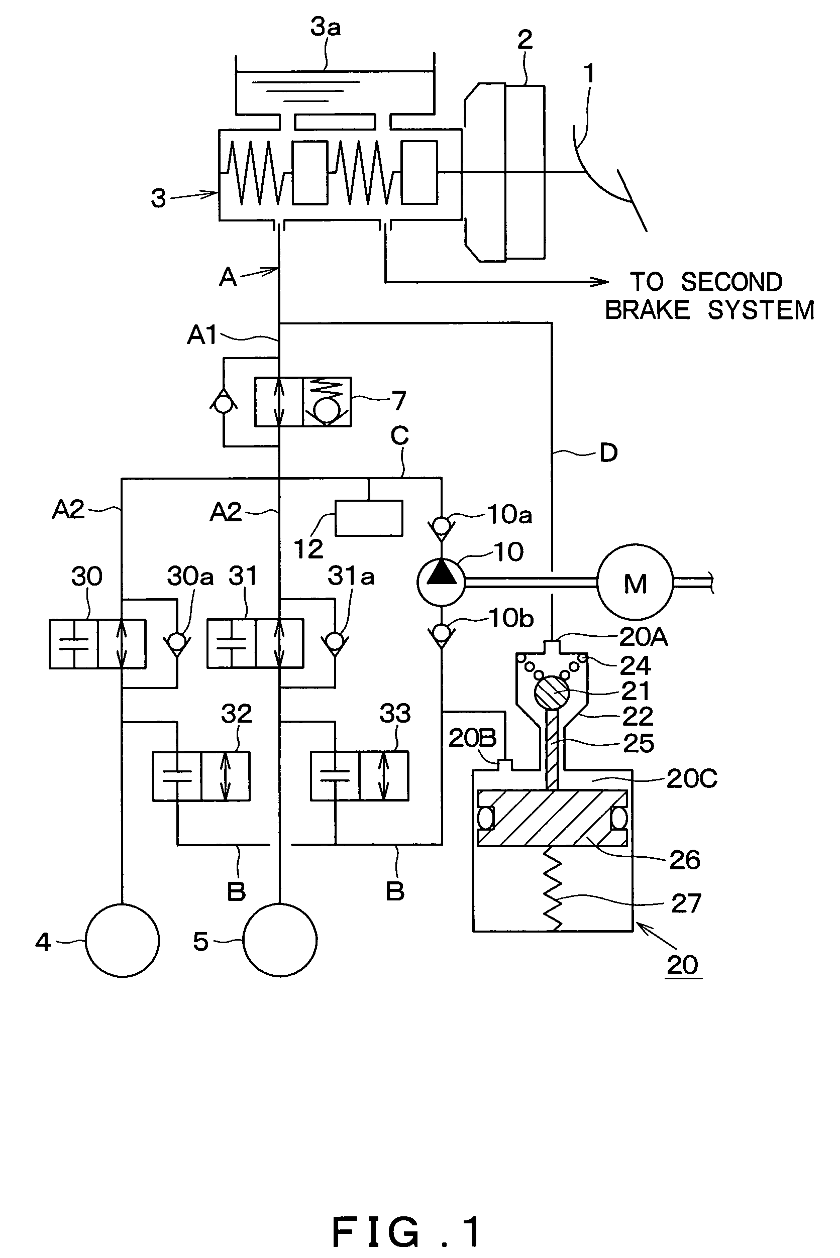
[0058]FIG. 1 shows a schematic brake conduit diagram of a brake apparatus which is applied to a pressure regulating reservoir according to an embodiment of the present invention. A basic structure of the brake apparatus will be described based upon FIG. 1. The embodiment describes an example for a front-wheel-drive four-wheeled vehicle, where the brake apparatus according to the present invention is applied to a vehicle with hydraulic circuits of an X brake conduit configuration. The X brake conduit configuration is provided with brake systems for the front right wheel-rear left wheel and front left wheel-rear right wheel.

[0059]A brake pedal 1 is depressed by a driver to apply a braking force to the vehicle. As shown in FIG. 1, the brake pedal 1 is connected to a brake booster 2 by which a pedal depression force is boosted.

[0060]The brake booster 2 includes a pushrod that transmits the boosted pedal depression force to a master cylinder 3. Pressing of this pushrod against a master p...

second embodiment

[0107]Hereinafter, a second embodiment of the present invention will be described. The brake apparatus provided with the pressure regulating reservoir shown in the present embodiment is basically identical to that in the first embodiment. Only portions specific to the pressure regulating reservoir are modified with respect to the first embodiment. Therefore, the description will focus only on portions that are different, and omit explanations of portions in the second embodiment identical to those in the first embodiment.

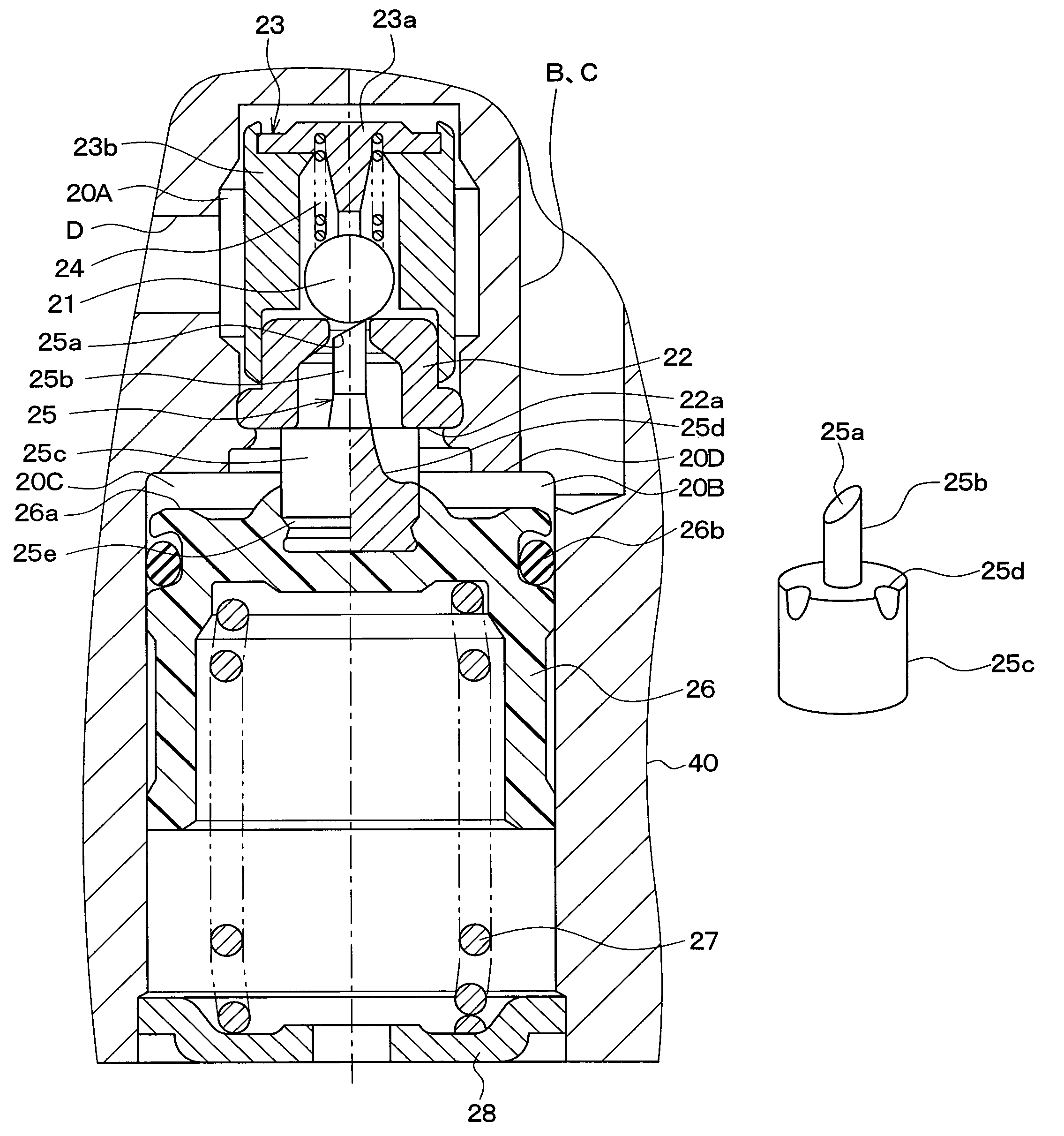
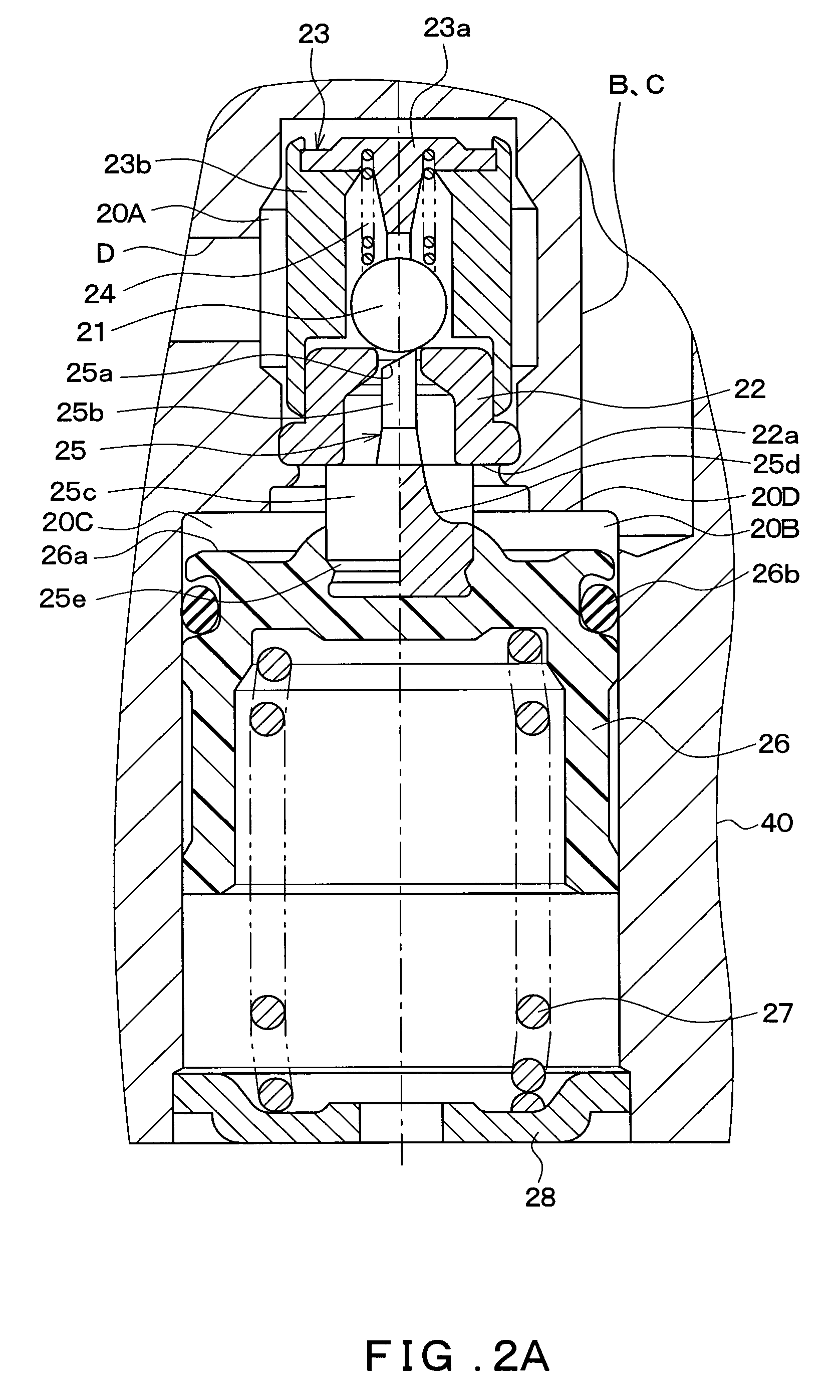
[0108]FIG. 4 shows a cross sectional structure of the pressure regulating reservoir 20 according to the present embodiment. In the first embodiment, the shaft 25 and the piston 26 are structured from different materials. However, both are made from the same material in the present embodiment.

[0109]As shown in FIG. 4, the shaft 25 and the piston 26 are structured from the same resin. Both may, for example, be formed through integral molding of resin.

[0110]In other wo...

third embodiment

[0111]Hereinafter, a third embodiment of the present invention will be described. The brake apparatus provided with the pressure regulating reservoir shown in the present embodiment is basically identical to that in the first embodiment. Only portions specific to the pressure regulating reservoir are modified with respect to the first embodiment. Therefore, the description will focus only on portions that are different, and omit explanations of portions in the third embodiment identical to those in the first embodiment.

[0112]FIG. 5A shows a partial enlarged cross sectional view of the vicinity of the shaft 25 of the pressure regulating reservoir 20 according to the present embodiment. Meanwhile, FIG. 5B shows the end of the shaft 25 when viewed from an upper side in the axial direction. In the first embodiment, the seat surface 25a is formed by inclining the end of the minor diameter portion 25b of the shaft 25. However in the present embodiment, the minor diameter portion 25b has a...


PUM


Abstract

A pressure regulating reservoir is structured such that a major diameter portion of a shaft contacts a bottom surface of a valve seat, whereas a top surface of a piston does not contact an upper end surface of a wall forming a reservoir chamber in a housing. Therefore, a lift amount of a ball valve can be set using a portion above the major diameter portion of the shaft that contacts the bottom surface of the valve seat. That is, the lift amount can be set using only a dimension in the axial direction of a minor diameter portion of the shaft.

Description

CROSS REFERENCE TO RELATED APPLICATION[0001]This application is based upon and claims the benefit of Japanese Patent Applications No. 2004-320412 filed on Nov. 4, 2004 and No. 2005-271959 filed on Sep. 20, 2005, the content of which are incorporated herein by reference.FIELD OF THE INVENTION[0002]The present invention relates to a pressure regulating reservoir that is applied to a brake hydraulic pressure control such as ABS control for a vehicle, and a vehicular braking apparatus using the pressure regulating reservoir.BACKGROUND OF THE INVENTION[0003]A vehicular braking apparatus that executes ABS control using a pressure regulating reservoir (switch reservoir) is disclosed in Japanese Patent Laid-Open Publication No. 2000-142346. The pressure regulating reservoir illustrated by Japanese Patent Laid-Open Publication No. 2000-142346 will be described with reference to FIG. 11.[0004]FIG. 11 is a cross sectional view showing a cross section of the pressure regulating reservoir. As sh...

Claims


Application Information

Patent Timeline
Patent Type & Authority Patents(United States)
IPC IPC(8): B60T8/42
CPCB60T8/4872
Inventor ARIKI, FUMIYOSHISASAKI, SHIN
Owner ADVICS CO LTD
Why Eureka
Try Eureka