Fuel tank system

Active Publication Date: 2016-05-19
TOYOTA JIDOSHA KK
View PDF1 Cites 0 Cited by
  • Summary
  • Abstract
  • Description
  • Claims
  • Application Information

AI Technical Summary

Benefits of technology

[0015]The extending member includes the cylindrical shaped base end cylinder, and the base end cylinder is in communication with the fuel tank through the tank communication path. The sliding lid section is provided so as to be capable of sliding with respect to the base end cylinder. The extending member is thereby configured so as to extend according to the pressure difference between the i

Problems solved by technology

In such a fuel tank system, gas flows vigorously from the fuel tank and into the vent pipe when the back pressure chamber of the valve member is opened to the atmosphere and the valve member is opened in a state of excessively high tank internal pressure inside the fuel tank.
The flow of gas

Method used


Image

  • Fuel tank system
  • Fuel tank system
  • Fuel tank system

Examples


Embodiment Construction

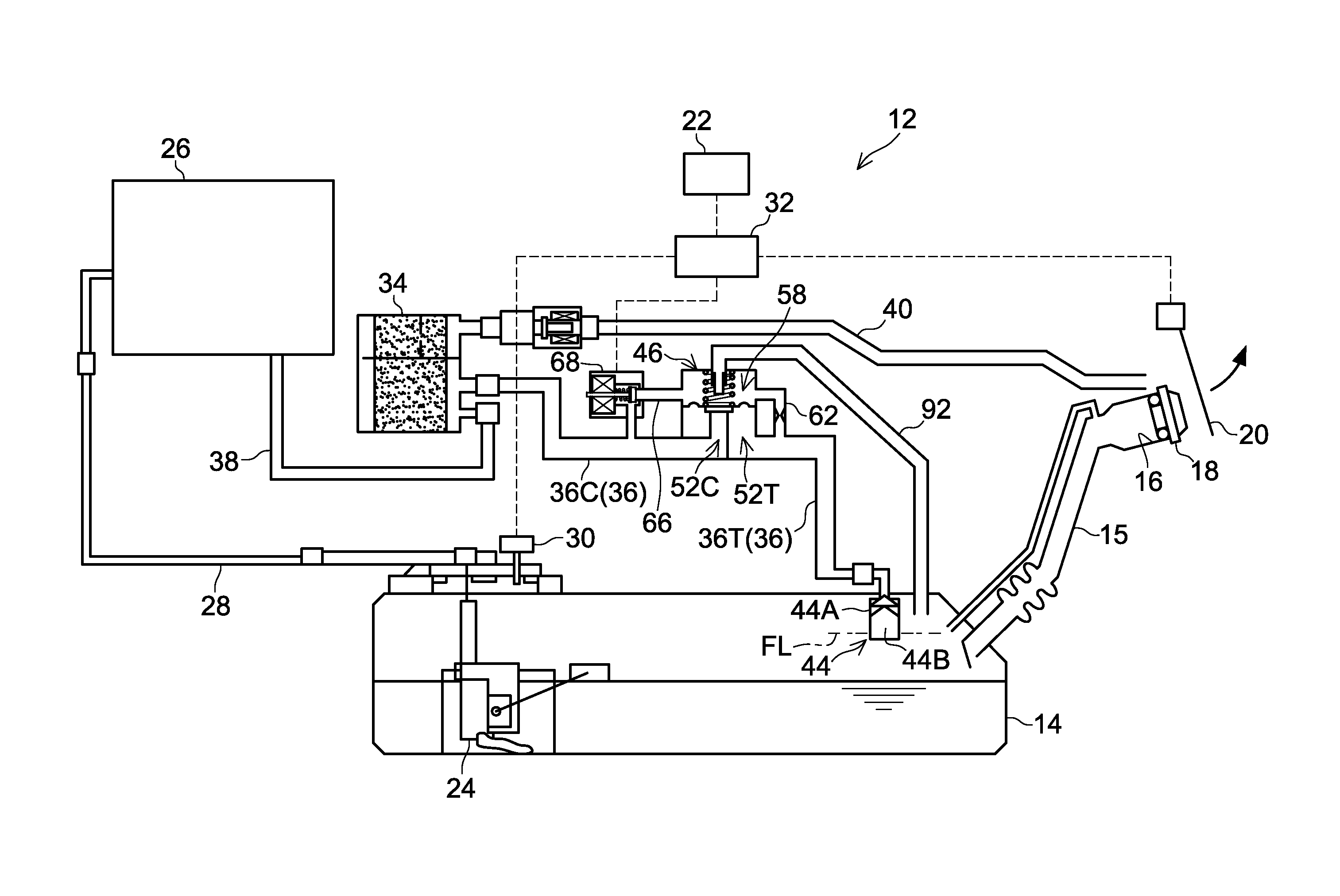
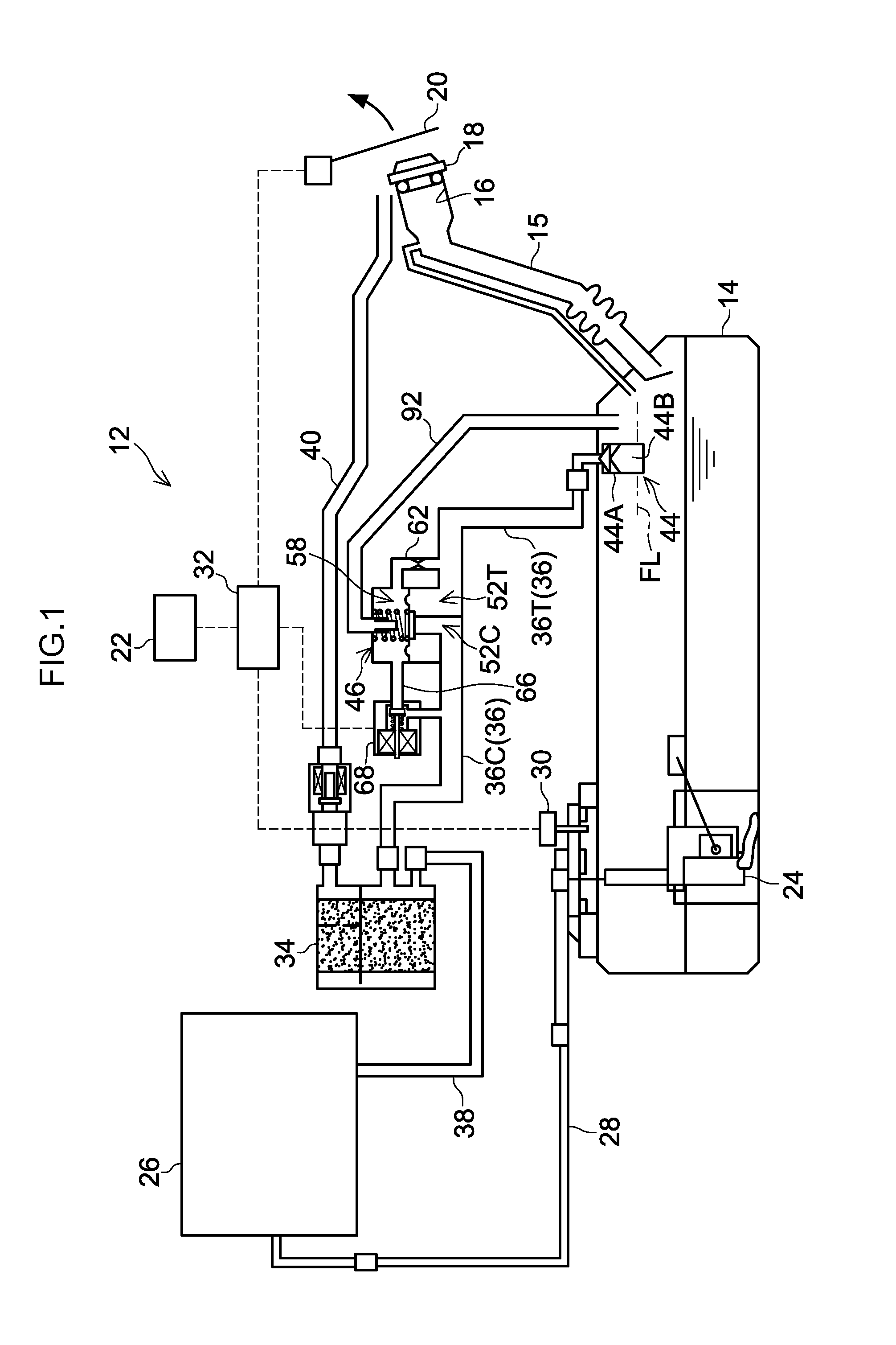
[0024]FIG. 1 illustrates a fuel tank system 12 of a first exemplary embodiment.

[0025]The fuel tank system 12 includes a fuel tank 14 capable of internally storing fuel. The upper portion of the fuel tank 14 is connected to a lower portion of an inlet pipe 15. An opening portion at the upper end of the inlet pipe 15 configures a fuel inlet 16. A fuel gun is inserted into the fuel inlet 16, enabling fuel to be supplied into the fuel tank 14. The fuel inlet 16 of the inlet pipe 15 is ordinarily closed off by a fuel cap 18, and the fuel cap 18 is removed by a fueling operator or the like when fueling.

[0026]A lid 20 is provided to a panel of the vehicle body, further to the outside than the fuel cap 18. The lid 20 is opened under specific circumstances, described below, by a control device 32 when information from operating a lid open switch 22 provided inside the vehicle cabin, or the like, is transmitted to the control device 32.

[0027]A fuel pump 24 is provided inside the fuel tank 14....


PUM


Abstract

A valve member is provided to a vent pipe for communicating a fuel tank with a canister. A solenoid valve is provided to a canister side bypass passage between a back pressure chamber of the valve member and the canister side vent pipe. An extending member is provided to restrict the valve lift amount in accordance with the internal pressure of the fuel tank.

Description

CROSS-REFERENCE TO RELATED APPLICATION[0001]This application claims priority under 35 USC 119 from Japanese Patent Application No. 2014-233909 filed on Nov. 18, 2014, the disclosure of which is incorporated by reference herein.BACKGROUND[0002]1. Technical Field[0003]The present invention relates to a fuel tank system.[0004]2. Related Art[0005]Fuel tank systems with a valve member (diaphragm valve) provided in a vent pipe for transporting gas inside a fuel tank to a canister are known (see, for example, Japanese Patent Application Laid-Open (JP-A) No. 2013-117181). In such fuel tank systems, ordinarily a valve member is placed in a closed state by causing the internal pressure of the tank to act on a back pressure chamber of a valve member, and hermetically close the fuel tank. When necessary, the valve member is placed in an open state by opening the back pressure chamber of the valve member to the atmosphere, and gas inside the fuel tank is transported to the canister. Moreover, in...

Claims


Application Information

Patent Timeline
IPC IPC(8): B60K15/035F02M25/08
CPCB60K15/03504F02M25/0854B60K2015/03566F02M25/089B60K2015/03585F02M25/0872B60K15/03519B60K2015/03509B60K2015/03514
Inventor SHIMOKAWA, SHINJI
Owner TOYOTA JIDOSHA KK
Why Eureka
Try Eureka