Fuel injection pump

a fuel injection pump and fuel injection technology, applied in the direction of pump, positive displacement liquid engine, liquid fuel engine, etc., can solve the problems of large impact and rubbing continuously, seal surface abrasion, seal surface cannot sit closely on the valve seat, etc., to achieve easy and accurate form of the valve seat in the insert piece, and the effect of reducing manufacturing cost and reducing maintenance cos

Active Publication Date: 2016-01-26
WOODWARD GOVERNOR CO +1
View PDF15 Cites 0 Cited by
  • Summary
  • Abstract
  • Description
  • Claims
  • Application Information

AI Technical Summary

Benefits of technology

[0012]The present invention constructed as the above brings the following effects.
[0013]According to the present invention, in the fuel injection pump, when the valve seat of the electromagnetic spill valve is worn with the passage of time, what is necessary is just to exchange the spill valve body and the insert piece having the valve seat. Namely, the components which need not be exchanged can be used continuously. Accordingly, the whole housing of the electromagnetic spill valve need not be constructed by material with high strength. In the electromagnetic spill valve, the insert piece can be shaped simply so as to form the valve seat in the insert piece easily and accurately. As a result, when number of the parts increased, the characteristics of the fuel injection pump can be maintained with the minimum maintenance cost without increasing the manufacturing cost.
[0014]Furthermore, according to the present invention, at the time of opening the electromagnetic spill valve, the spill valve body can be slid toward the other side in the axial direction of the insert piece until the end at the other side of the spill valve body reaches the position the same as the end at the other side of the insert piece. Namely, the lift amount of the spill valve body at the time of opening the electro-magnetic spill valve is equal to the distance between the end at the other side of the spill valve body and the end at the other side of the insert piece in the axial direction in the state in which the seal surface of the spill valve body has sit on the valve seat of the insert piece, that is, at the time of opening the electromagnetic spill valve. Accordingly, in the electromagnetic spill valve, by only changing the positional relation between the end at the other side of the spill valve body and the end at the other side of the insert piece, the lift amount of the spill valve body can be controlled. As a result, the lift amount of the spill valve body can be controlled easily and accurately, whereby the manufacturing cost and the maintenance cost can be reduced.
[0015]Furthermore, according to the present invention, the spill valve body is guided by only the insert piece. Accordingly, in the electromagnetic spill valve, the spill valve body can be installed accurately. As a result, the sitting accuracy of the valve seat of the insert piece and the seal surface of the spill valve body can be improved so as to suppress the amount of abrasion, whereby the maintenance cost can be reduced.
[0016]Furthermore, according to the present invention, in the electromagnetic spill valve, the lift amount of the spill valve body can be controlled by only changing the position of the touching surface of the stopper by exchanging the shim. Accordingly, it is not necessary to have the plurality of the stopper having different positions of the touching surface as stock parts for the control. As a result, the cost of the stock parts for the control can be reduced, and the lift amount of the spill valve body can be controlled easily and accurately, whereby the manufacturing cost and the maintenance cost can be reduced.

Problems solved by technology

In the electromagnetic spill valve, a spill valve body is opened and closed complicatedly and quickly corresponding to the driving state of the engine, whereby large impact and rubbing occur continuously.
As a result, abrasion occurs in a seal surface and a valve seat, whereby the seal surface cannot sit closely on the valve seat and fuel leaks.
Accordingly, for improving abrasion resistance of the seal surface and the valve seat, it is necessary to construct the spill valve body and the whole housing with material having high strength, whereby the manufacturing cost is increased.
However, in such an art as shown in the Patent Literature 1, when the abrasion in the seat part and the valve seat part is advanced and the effect of reduction of fuel leakage by the softer material cannot be obtained, the whole electromagnetic spill valve must be exchanged for maintain the sealing characteristic of the electromagnetic spill valve.
Namely, there is a problem in that construction members of the electromagnetic spill valve which do not need to be exchanged are exchanged simultaneously, whereby the maintenance cost which is not necessary essentially is caused.

Method used


Image

  • Fuel injection pump
  • Fuel injection pump
  • Fuel injection pump

Examples


Embodiment Construction

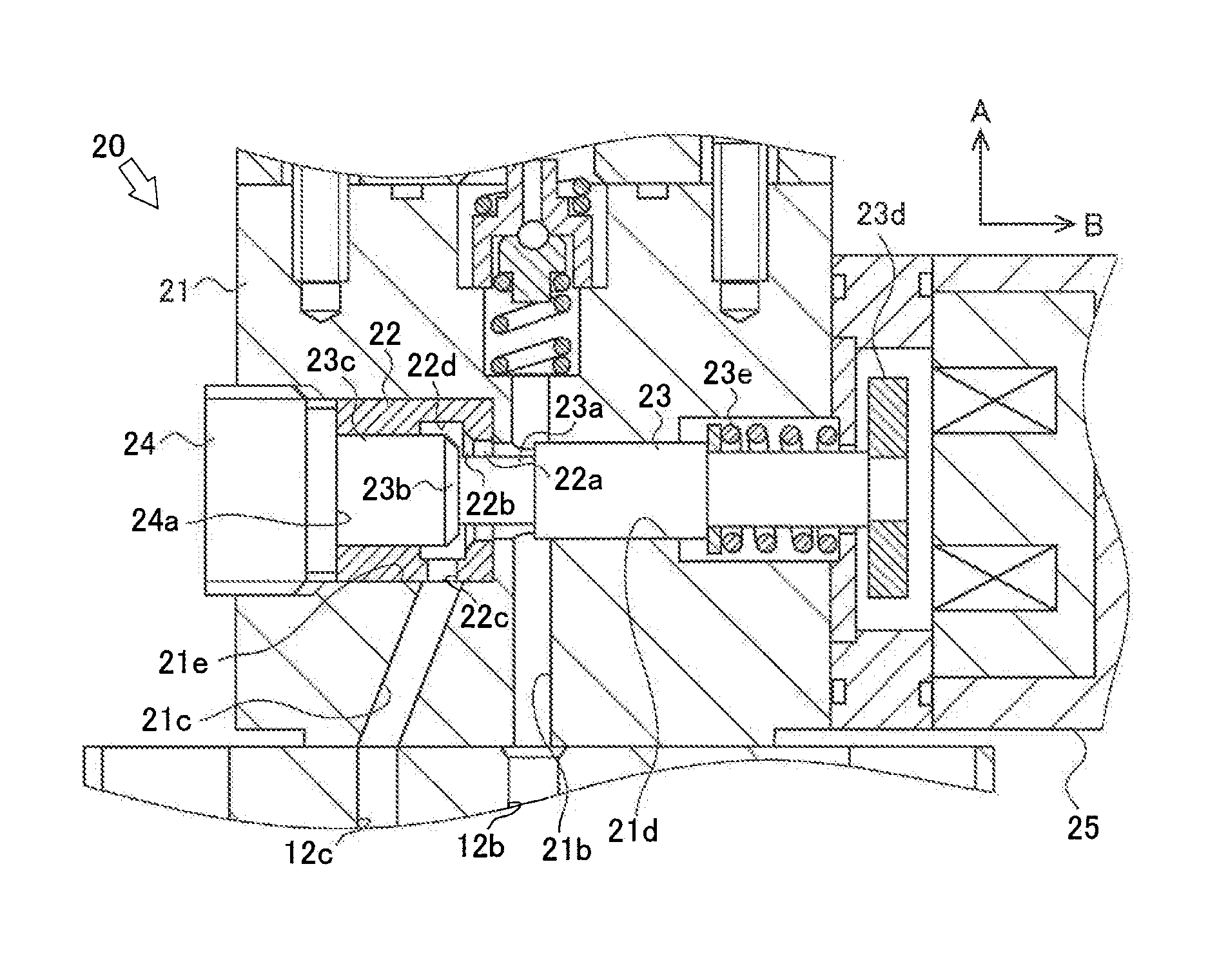
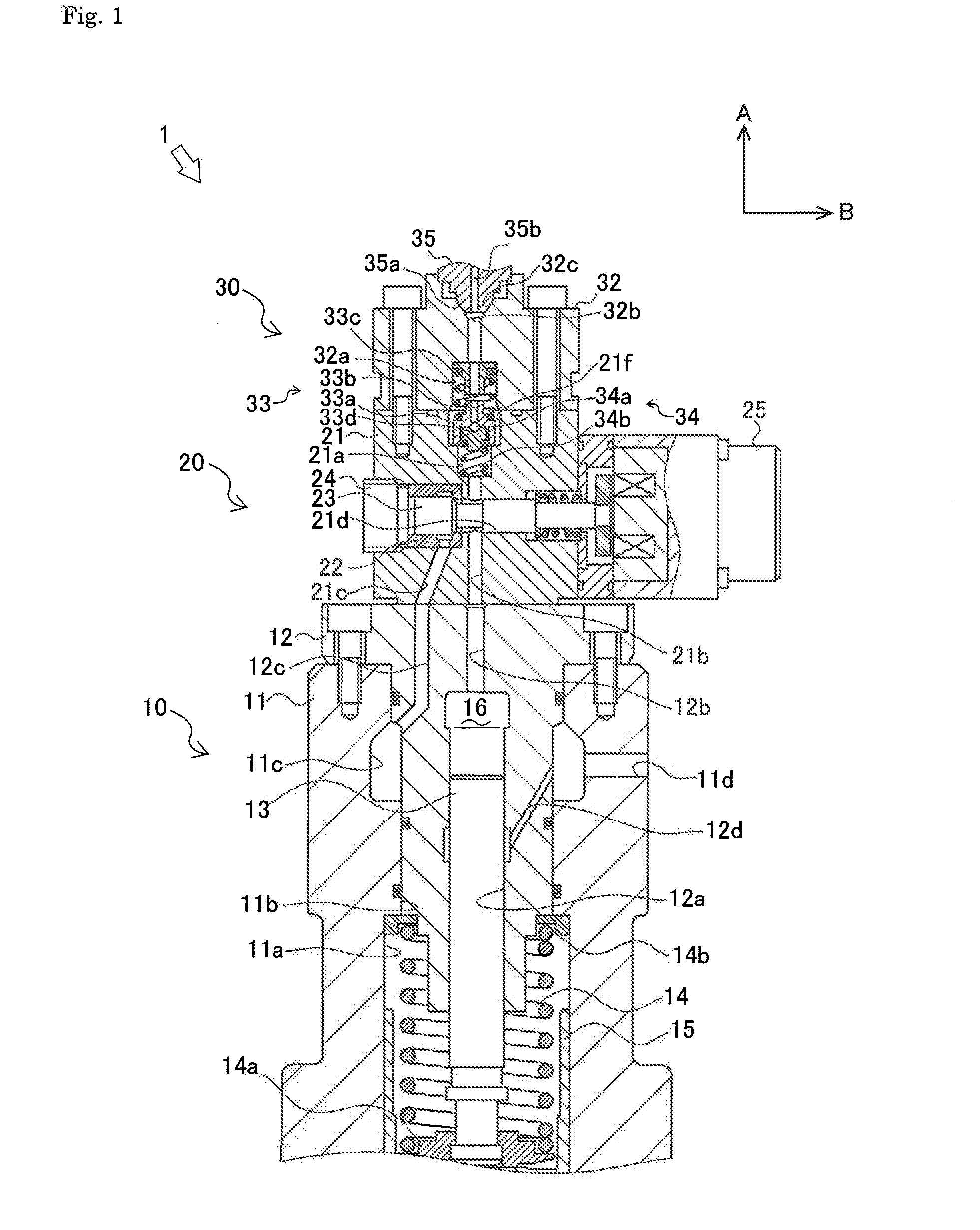
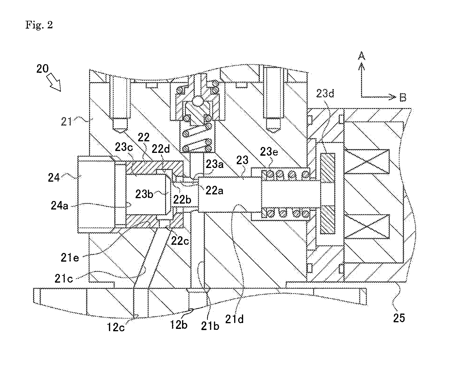
[0037]Next, an explanation will be given on a fuel injection pump 1 which is a fuel injection pump according to a first embodiment of the present invention referring to FIGS. 1 and 2. Hereinafter, a direction of an arrow A is regarded as the upward direction so as to prescribe the vertical direction, and a direction of an arrow B is regarded as the rightward direction so as to prescribe the lateral direction.

[0038]As shown in FIG. 1, the fuel injection pump 1 is connected to a low-pressure pump (feed pump), not shown, and compresses fuel from the low-pressure pump and supplies it to a fuel injection nozzle (not shown). The fuel injection pump 1 has a pump body part 10, an electromagnetic spill valve 20 and a two-way delivery valve part 30.

[0039]The pump body part 10 includes a pump body 11, a barrel 12, a plunger 13, a plunger spring 14, a tappet 15, a cam (not shown) and the like.

[0040]The pump body 11 is substantially cylindrical. In the axis part of the lower end surface of the p...


PUM


Abstract

A fuel injection pump is provided which can be manufactured without an increase in the manufacturing cost and which is configured so that the sealing performance of an electromagnetic spill valve can be maintained with minimum maintenance cost.

Description

TECHNICAL FIELD[0001]The present invention relates to a fuel injection pump mounted on a diesel engine.BACKGROUND ART[0002]Conventionally, a fuel injection pump mounted on a large diesel engine is known in which timing and number of times of fuel injection is controlled corresponding to the driving state of the engine for improving fuel efficiency and reducing exhaust gas emission. In such a fuel injection pump, an electromagnetic spill valve is opened and closed at optional timing so as to perform accurate fuel injection.[0003]In the electromagnetic spill valve, a spill valve body is opened and closed complicatedly and quickly corresponding to the driving state of the engine, whereby large impact and rubbing occur continuously. As a result, abrasion occurs in a seal surface and a valve seat, whereby the seal surface cannot sit closely on the valve seat and fuel leaks. Accordingly, for improving abrasion resistance of the seal surface and the valve seat, it is necessary to construct...

Claims


Application Information

Patent Timeline
Patent Type & Authority Patents(United States)
IPC IPC(8): F04B53/10F04B7/00F02M59/46F02M59/36F02M63/00F02M59/10
CPCF02M59/466F02M59/366F02M59/462F02M63/0033F02M63/0077F02M59/102F02M2200/02F02M2200/04F02M2200/315
Inventor EGASHIRA, TAKANORISONE, KAZUTAKAUMEDA, SHINYAKIECHLE, STEFAN
Owner WOODWARD GOVERNOR CO
Why Eureka
Try Eureka