
Propagation based electromagnetic measurement of anisotropy using transverse or tilted magnetic dipoles

a technology of magnetic dipoles and propagation based electromagnetic measurement, which is applied in the direction of reradiation, detection using electromagnetic waves, instruments, etc., can solve the problems of affecting measurement, complicating the evaluation and characterization of potential and existing hydrocarbons, and affecting measurement results

Inactive Publication Date: 2006-02-14
SCHLUMBERGER TECH CORP
View PDF38 Cites 86 Cited by
  • Summary
  • Abstract
  • Description
  • Claims
  • Application Information

AI Technical Summary

Benefits of technology

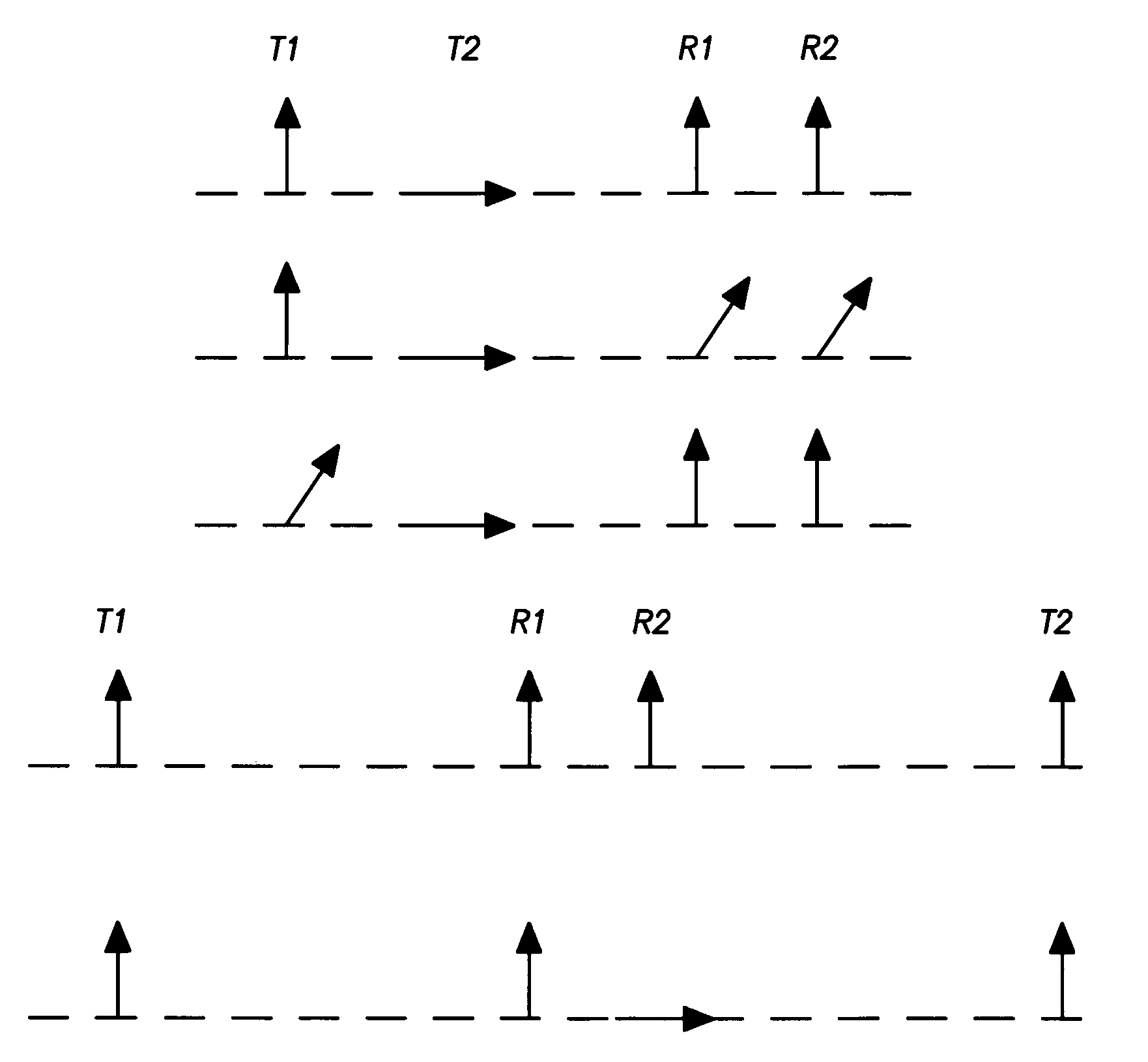
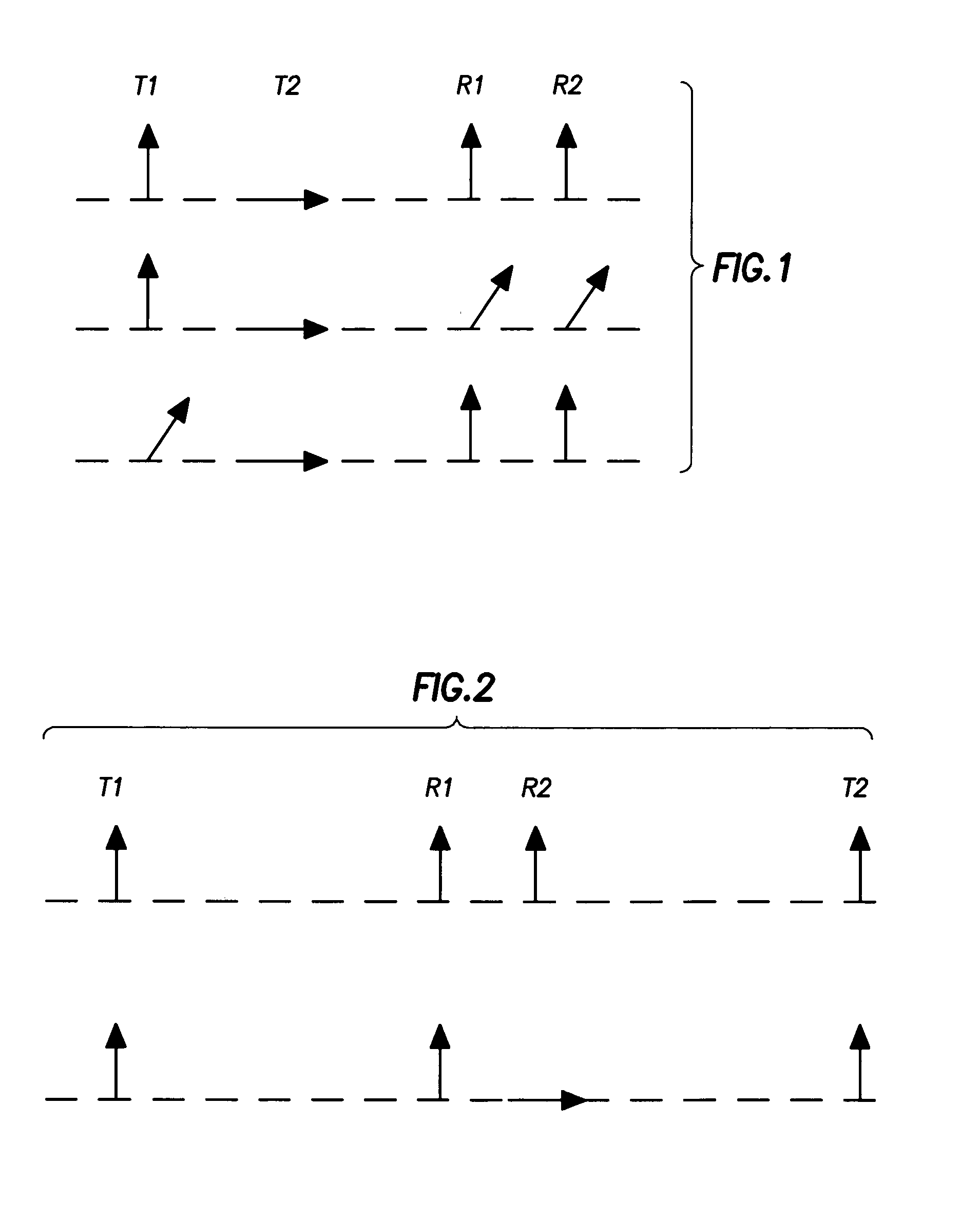
The invention provides a well logging system and method for determining an anisotropy parameter of a subsurface formation. The system includes an elongated support with a longitudinal axis and adapted for subsurface disposal while drilling a borehole through the formation. The system includes multiple transmitter antennas and receiver antennas with their axes oriented at an angle with respect to the support axis. The processor means combines detected electromagnetic signals associated with the transmitter or receiver antennas to determine the anisotropy parameter. The technical effect of the invention is to provide a more accurate and reliable method for determining the anisotropy parameter of a subsurface formation, which is important for the evaluation of oil and gas reservoirs.

Problems solved by technology

The measurements are also affected by mud filtrate invasion that changes the properties of the rock near the wellbore.
Resistivity anisotropy is a characteristic of subsurface earth formations that can complicate the evaluation and characterization of potential and existing hydrocarbon-bearing zones.

Method used


Image

  • Propagation based electromagnetic measurement of anisotropy using transverse or tilted magnetic dipoles
  • Propagation based electromagnetic measurement of anisotropy using transverse or tilted magnetic dipoles
  • Propagation based electromagnetic measurement of anisotropy using transverse or tilted magnetic dipoles

Examples


Embodiment Construction

[0028]In propagation logging, a high-frequency alternating current is sent through the transmitter antenna. The alternating magnetic field created in the transmitter produces currents (eddy currents) in the formation surrounding the borehole. The ground loop currents are directly proportional to the formation conductivity. The voltage detected at the receiver(s) is proportional to the ground loop currents and, therefore, to the conductivity of the formation.

[0029]It is well known that in the low frequency limit, the real part of TMD-antenna coupling in vertical wells is proportional to vertical conductivity. That suggests the use of a low frequency induction-type measurement at conventional induction tool frequencies. However, induction measurements are not always practical in LWD operations. Instead, propagation measurements at substantially higher frequencies are commonly used. As the frequency increases, the tool responses become sensitive to a combination of horizontal and verti...


PUM


Abstract

Transverse or tilted magnetic dipole antenna systems are used for electromagnetic logging measurements to determine the anisotropic resistivity of subsurface formations. Combined measurements between transverse or tilted antennas, as well as axial antennas, are used to compensate for receiver antenna mismatch in the system. Some embodiments use model-based parametric inversion to estimate the anisotropic resistivity in the presence of invasion and shoulder-bed effects.

Description

CROSS REFERENCE TO RELATED APPLICATIONS[0001]This present application claims the benefit of U.S. Provisional Application No. 60 / 374,163 filed Apr. 19, 2002.BACKGROUND OF INVENTION[0002]1. Field of the Invention[0003]The present invention is generally directed to the analysis of underground earth formations, and, more particularly, to the determination of formation resistivity properties and / or profiles.[0004]2. Description of Related Art[0005]Electromagnetic (EM) logging tools have been employed in the field of subsurface exploration for many years. These logging tools or instruments entail an elongated support equipped with antennas that are operable as sources or sensors. The antennas on these tools are generally formed as loops or coils of conductive wire. In operation, a transmitter antenna is energized by an alternating current to emit EM energy through the borehole fluid (“mud”) and into the surrounding formations. The emitted energy interacts with the borehole and formation t...

Claims


Application Information

Patent Timeline
Patent Type & Authority Patents(United States)
IPC IPC(8): G01V3/10G01V3/30
CPCG01V3/30
Inventor OMERAGIC, DZEVATTABANOU, JACQUES R.DUMONT, ALAIN
Owner SCHLUMBERGER TECH CORP
Learn More