
Method and system for monitoring the wheels of motor vehicle

a technology for motor vehicles and wheels, applied in vehicle tyre testing, instruments, roads, etc., can solve the problems of complex and therefore expensive hardware and software needed to determine the position of wheels, and achieve the effect of small hardware expenditur

Inactive Publication Date: 2006-02-14
CONTINENTAL AUTOMOTIVE GMBH
View PDF34 Cites 17 Cited by
  • Summary
  • Abstract
  • Description
  • Claims
  • Application Information

AI Technical Summary

Benefits of technology

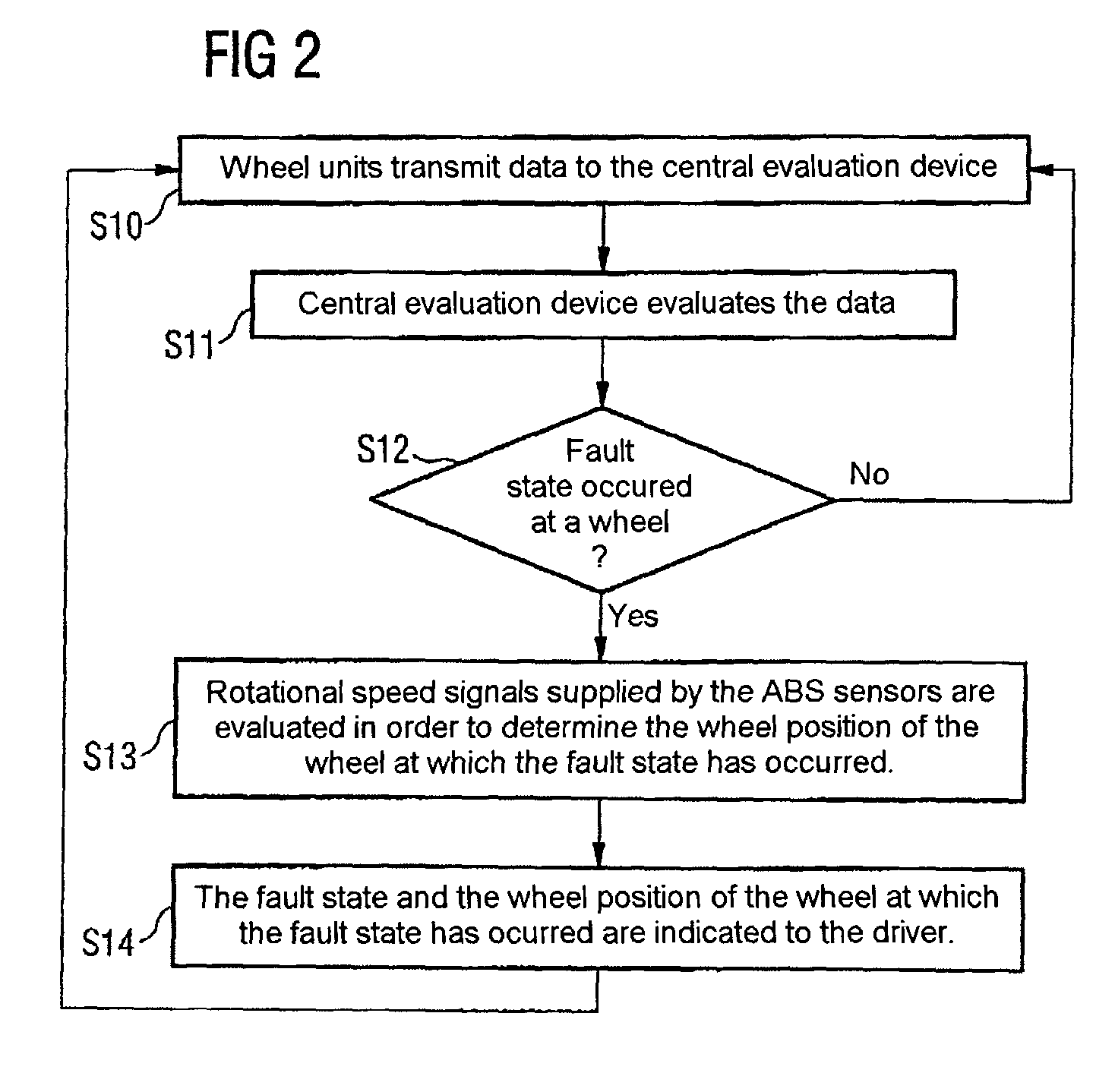
[0019]The method according to the invention is based on the prior art of the generic type in that each wheel to be monitored is assigned a wheel unit which monitors the respective wheel for fault states, and in that at least the wheel position of a wheel at which a fault state has occurred is determined by means of output signals of sensors of the antilock brake system. As a result of this solution it is, for example, no longer absolutely necessary for the wheel units to transmit individual identifiers to the central evaluation device, as a result of which the wheel units can be implemented with a smaller degree of expenditure on hardware and software, which reduces costs. In the case of tire pressure monitoring, the wheel units permit more precise measurement of the air pressure than is possible by means of the output signals of the sensors of the antilock brake system, with the result that the invention combines the precision of measurement results which can be achieved using wheel units with the cost-effective assignment of the wheels to wheel positions by means of the antilock brake system.

Problems solved by technology

The known systems and methods have in common the fact that they are very complex and therefore expensive in terms of the hardware and software necessary to determine the wheel positions.

Method used


Image

  • Method and system for monitoring the wheels of motor vehicle
  • Method and system for monitoring the wheels of motor vehicle
  • Method and system for monitoring the wheels of motor vehicle

Examples


Embodiment Construction

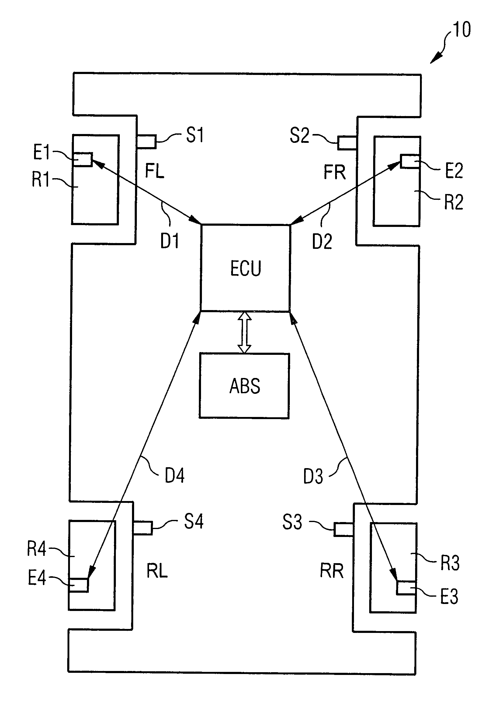
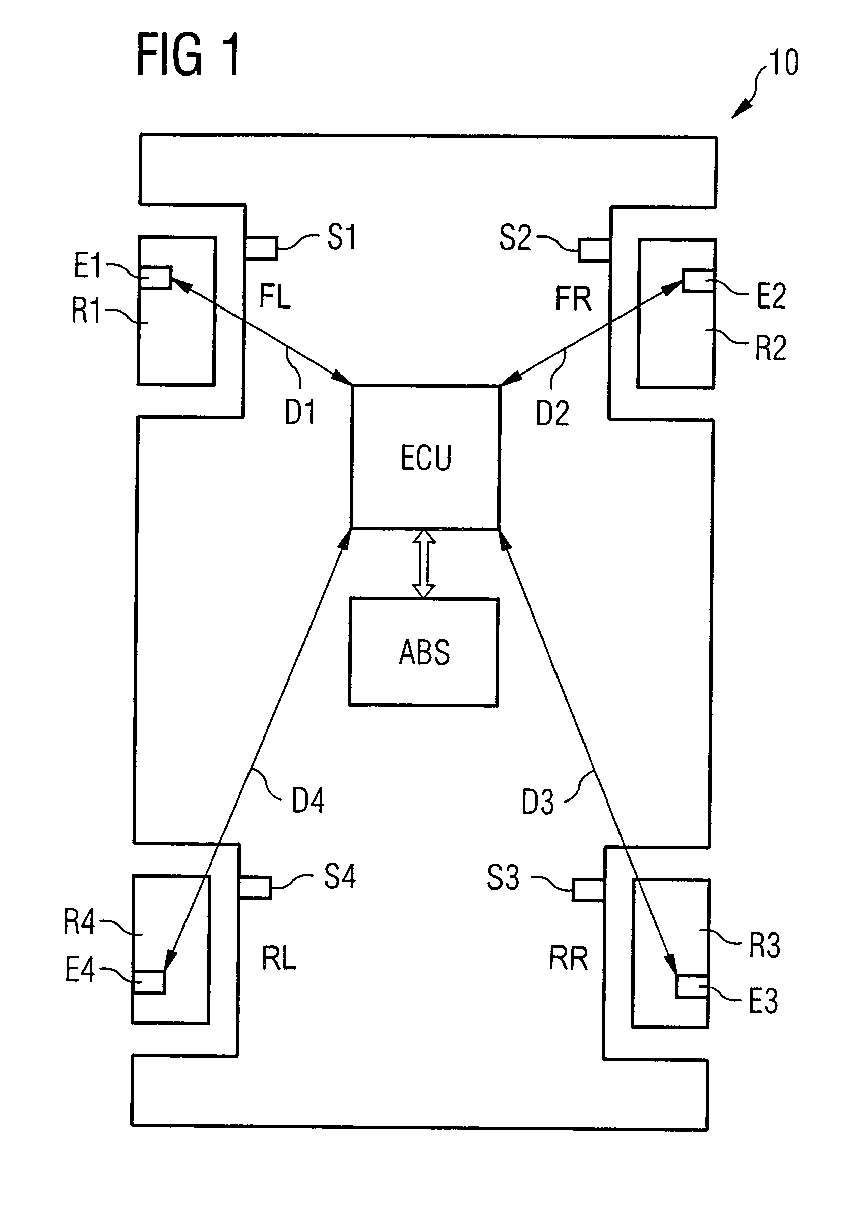
[0031]FIG. 1 shows a schematic block diagram of a motor vehicle which has an embodiment of the system according to the invention. Here, the entire motor vehicle is provided with the reference symbol 10. The motor vehicle 10 has four wheels R1, R2, R3, R4. Each of the wheels R1, R2, R3, R4 is assigned a wheel unit E1, E2, E3, E4 which can be arranged, for example, in the tire and / or in the region of the valve of the respective wheel R1, R2, R3, R4. The wheel position front left is referred to as FL, the wheel position front right is referred to as FR, the wheel position rear left is referred to as RL and the wheel position rear right is referred to as RR. In the region of the wheels R1, R2, R3, R4, a sensor S1, S2, S3, S4 of the antilock brake system ABS is arranged in each case on the chassis in a manner known per se, the connecting lines between the sensors S1, S2, S3, S4 to the ABS control unit not being illustrated. The antilock brake system ABS is connected to a central evaluati...


PUM


Abstract

The method comprises the steps of monitoring the wheels (R1, R2, R3, R4) of a motor vehicle having an antilock brake system (ABS), for fault states, in particular for incorrect tire pressures, the occurrence of a fault state and the wheel position (FL, FR, RL, RR) of the wheel (R1, R2, R3, R4) at which the fault state has occurred being indicated. Each wheel (R1, R2, R3, R4) to be monitored is assigned a wheel unit (E1, E2, E3, E4) which monitors the respective wheel (R1, R2, R3, R4) for fault states, and wherein at least the wheel position (FL, FR, RL, RR) of a wheel (R1, R2, R3, R4) at which a fault state has occurred is determined by means of output signals of sensors (S1, S2, S3, S4) of the antilock brake system (ABS).

Description

BACKGROUND OF THE INVENTION[0001]The invention relates to a method for monitoring the wheels of a motor vehicle having an antilock brake system for fault states, in particular for incorrect tire pressures, the occurrence of a fault state and the wheel position of the wheel at which the fault state has occurred being indicated. In addition, the invention relates to a system for monitoring the wheels of a motor vehicle having an antilock brake system, for fault states, in particular for incorrect tire pressures, the system indicating the occurrence of a fault state and the wheel position of the wheel at which the fault state has occurred.[0002]The term fault state is to be interpreted loosely in the present context and comprises all states which are considered to be worthy of detection.[0003]With respect to the systems of the generic type and the methods of the generic type it is known, for example, that the wheel units transmit information to a central evaluation device, arranged on ...

Claims


Application Information

Patent Timeline
Patent Type & Authority Patents(United States)
IPC IPC(8): B60C23/00B60C23/04B60C23/06
CPCB60C23/061B60C23/0416
Inventor BERGERHOFF, NIKOLASFISCHER, MARTIN
Owner CONTINENTAL AUTOMOTIVE GMBH
Learn More