[0017]It is an object of an exemplary embodiment of the present invention to provide a condensation dryer in which a component arranged in the process air channel, in particular a heat exchanger, may be easily cleaned. Preferably, the cleaning is intended to be able to be undertaken automatically or in a manner which is controllable by a user.
[0024]Preferably, the closure part of the rinsing container is connected to a bistable spring arrangement which may be actuated for opening the outlet region of the rinsing container closed by the closure part. This has the
advantage that the closure part of the rinsing container may be particularly reliably opened by the bistable action of the spring arrangement. The relevant opening may thus preferably take place particularly rapidly, as the relevant bistable spring arrangement is provided with a spring function for switching into its respective bistable position. For actuating the bistable spring arrangement, preferably a thermorelay or magnetic
relay is provided coupled thereto. This has the
advantage that a particularly small amount of expenditure is sufficient for activating the bistable spring arrangement.
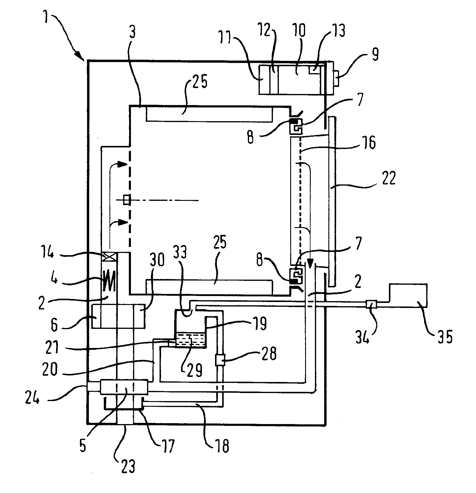
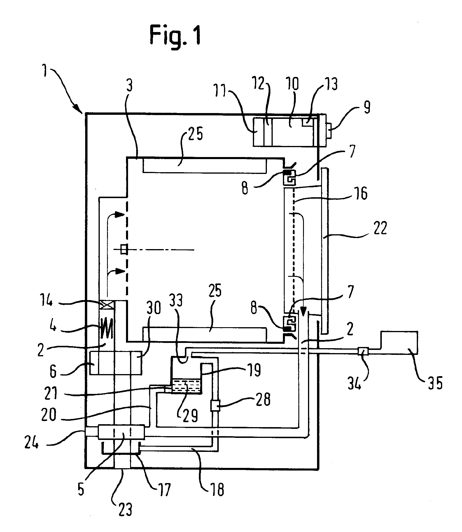
[0025]According to an advantageous embodiment of the present invention, in a heat exchanger forming the aforementioned component, the rinsing fluid is discharged to a heat exchanger region preferably merely located at a specific distance from the inlet region of the process air into the heat exchanger. This has the
advantage that deposits in the form of lint which are generally increasingly produced in the entire inlet region of the heat exchanger may be effectively removed. Thus the
discharge of the rinsing fluid is preferably carried out directly or shortly after finishing a drying cycle of laundry to be dried, as at this time soiling, in particular lint adhering to the component and / or heat exchanger, is still damp or solubilized and relatively easily removable by the discharged rinsing fluid. At this time, moreover, the condensate tank and / or rinsing container are generally filled with condensate which may be used for cleaning the component, for example a heat exchanger. Moreover, generally after each drying cycle a longer time passes until the next drying cycle so that
sufficient time remains for removing the rinsing fluid.
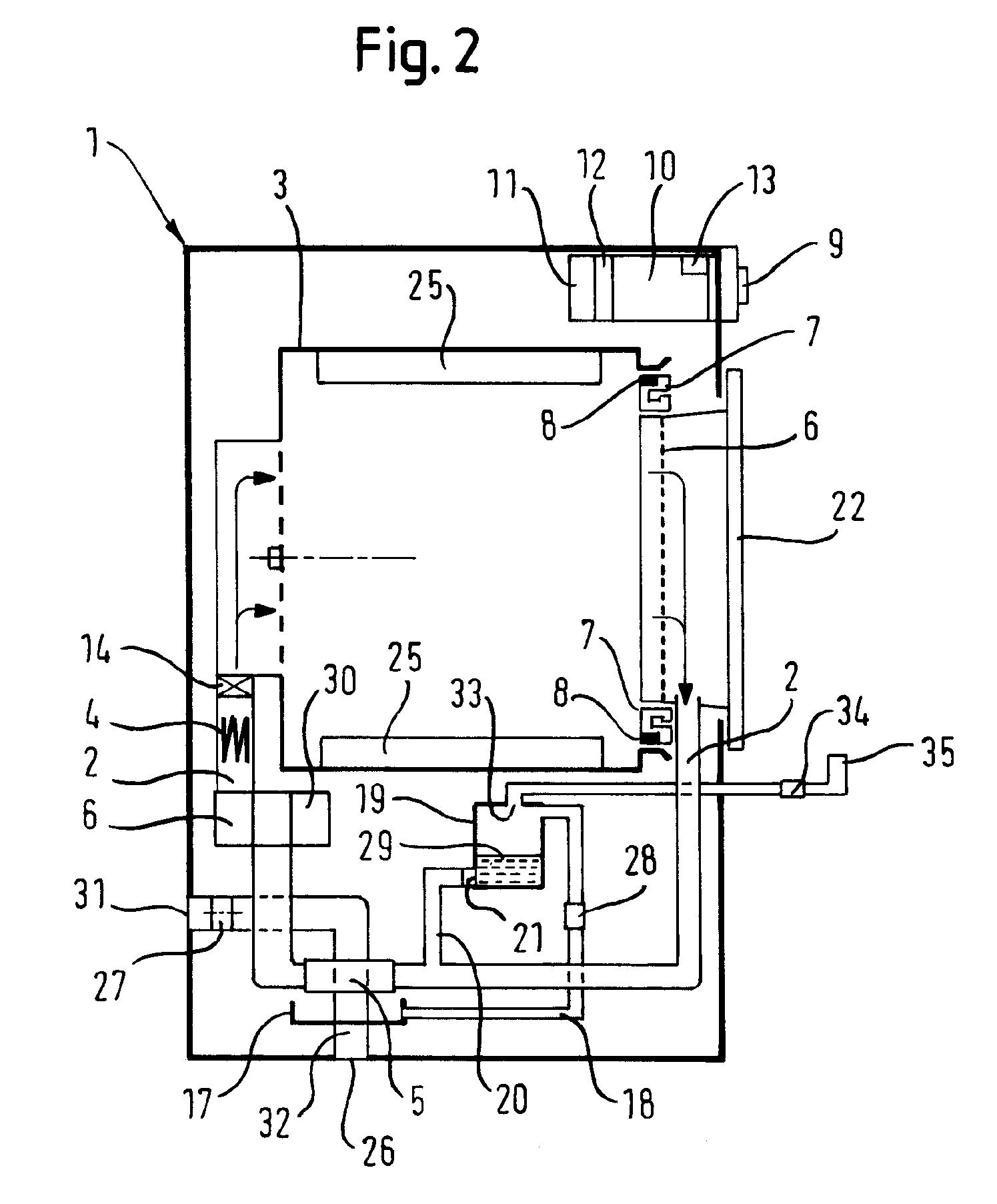
[0026]According to a further advantageous embodiment of the present invention, in a heat exchanger forming the aforementioned component the rinsing fluid is supplied by mechanical, hydraulic, pneumatic or electromechanical deflection of a starting region provided at the inlet region of the process air into the heat exchanger, as far as an end region located at a distance therefrom in the direction of the outlet region of the process air from the heat exchanger. This has the advantage that the component to be cleaned, in this case in particular a heat exchanger, may be cleaned in a relatively simple manner via a specific region. The relevant region may thus extend from the inlet region of the process air into the heat exchanger as far as the outlet region thereof from the heat exchanger. The supply of rinsing fluid is also in this case preferably carried out directly or shortly after finishing a drying cycle of damp laundry to be dried, as at this time, soiling, in particular lint adhering to the aforementioned component, is still damp and able to be easily removed by the rinsing fluid discharged in a surge-like manner.
[0031]This has the advantage of a low appliance cost for particularly efficient cleaning of a component arranged within a process air channel of a
washer dryer or dryer. By sudden opening of the rinsing container, in particular, the condensate collected in the rinsing container, possibly topped up with a quantity of mains water from the
water supply, is discharged efficiently and rapidly as a water surge to the component to be cleaned, without additional devices being required.
[0052]An exemplary embodiment of the invention has the advantage that in a condensation dryer, irrespective of the presence of condensate and / or a sufficient quantity of condensate, a cleaning of components in the process air channel may be carried out in a simple and efficient manner. Thus, the heat exchanger of the condensation dryer may be cleaned automatically or by the intervention of a user. In embodiments of the invention, a cleaning requirement of a heat exchanger may be determined without the additional necessity of opening the condensation dryer. The invention is, in particular, advantageous when using a
heat pump, as the
heat sink of a heat pump generally may not be removed from the condensation dryer for cleaning. The heat exchanger of the condensation dryer may also be easily and readily cleaned without mechanical intervention on the appliance. For cleaning, neither brushes, filters or the like are required. As the invention permits regular cleaning of the heat exchanger according to requirements, a dryer with improved efficiency and a markedly
reduced susceptibility to breakdown is possible.

